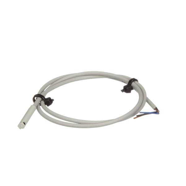
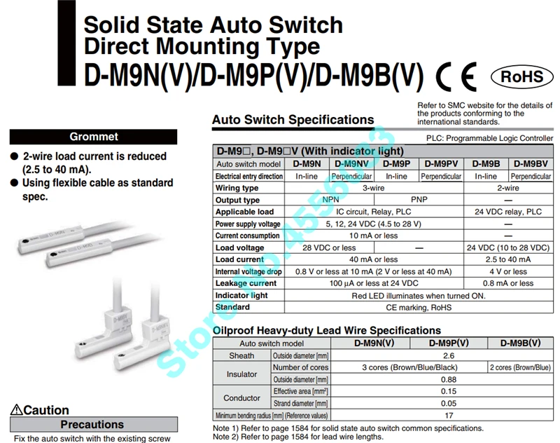
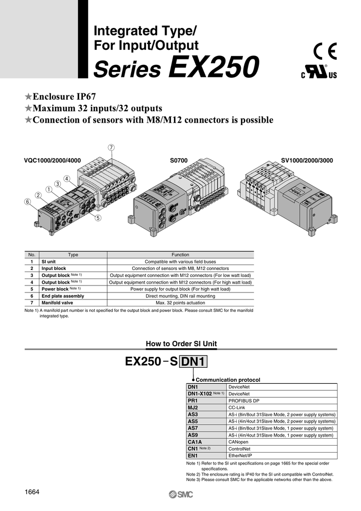
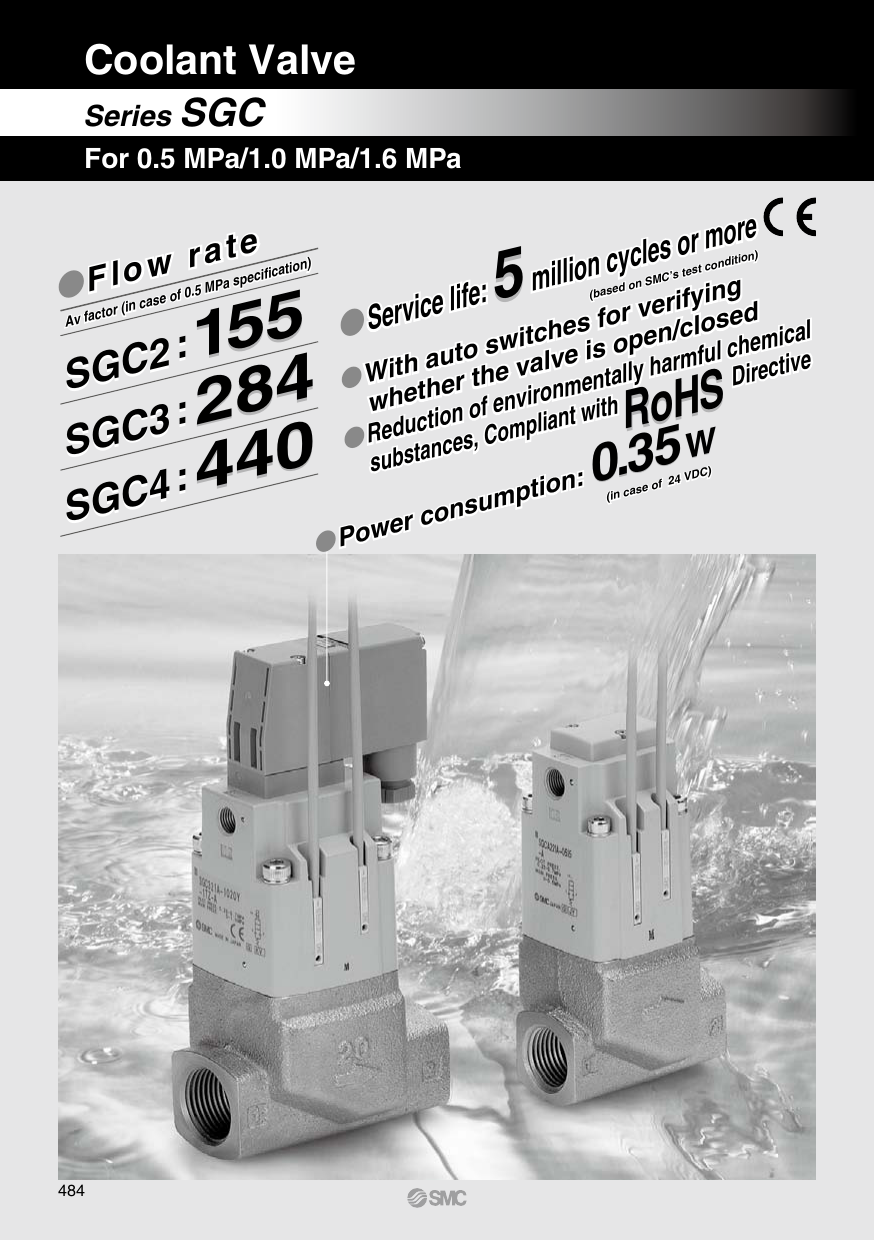
Sensor solid state direct mount grommet connection for mxmhcq2ncq2ncq8 download datasheet. Further use dc power with sufficient capacity and a low rip.
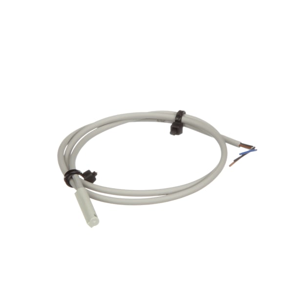
D M9n
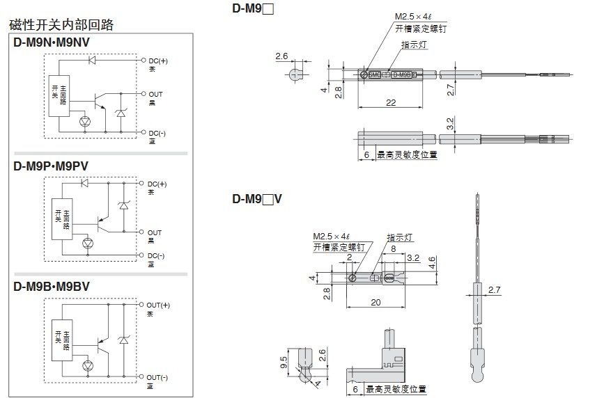
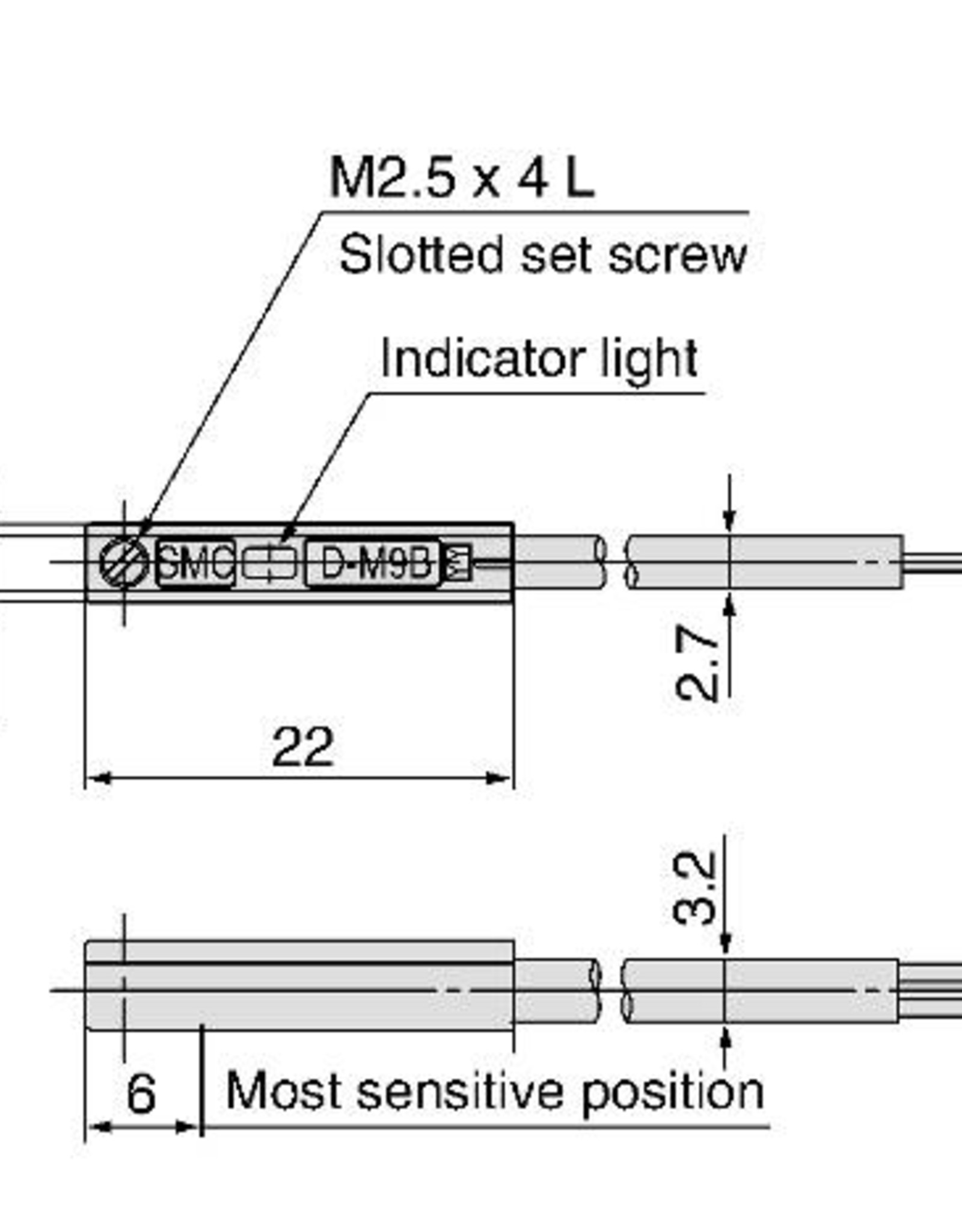
Smc d m9b wiring diagram. D m9b allied stock. Flexibility is 15 times greater than the conventional model smc comparison. Dimensions d m9 2 wire load current is reduced 25 to 40 ma. Mixed single and double wiring is available as. Complies with the basic safety principles in accordance with iso 13849 load operating time ms explosion may result. Station wiring wiring side 1 for single wiring sq1000 017 to 023nm sq2000 025 to 035nm sq12000 tfj38gb 20 26 1 2 3 double wiring connected to sol.
Note 2 refer to page 1194 for lead wire lengths. Proceed carefully as incorrect wiring can cause damage. Smc corporation smc corporation d m9b. Specifications or less or less operating original instructions load supply internal voltage minimum operating voltage drop of switch voltage of load model number d a93 d a93v d a96 d a96v d a90 d a90v wiring style 2 wire type 3 wire type 2 wire type application plc ic circuit plc ic circuit load voltage. D m9n d m9p d m9b 7 13 38 63 g lead wire length grommet note 1 refer to page 1194 for solid state auto switch common specifications. Series image for reference only.
Email item price. Electronic regulator wiring wiring caution. Connect the cable to the connector on the body with the wiring arranged as show below. The intended use of this product is to detect a position of a magnet in a pneumatic cylinder. Validated d m9 components according to iso 13849. Smc d m9b high flex solid state aswitch auto switch accessory part number.
Or copy this link to share. Series d m9n d m9p d m9b 1 wiring should be kept as short as possible. Wiring wiring on the double single low no. B is used for the internal wiring of each station regardless of valve and option types. Series image for reference only please pull down this page to review full catalog specifications pdf.


