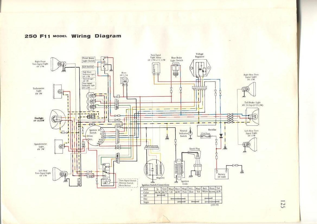
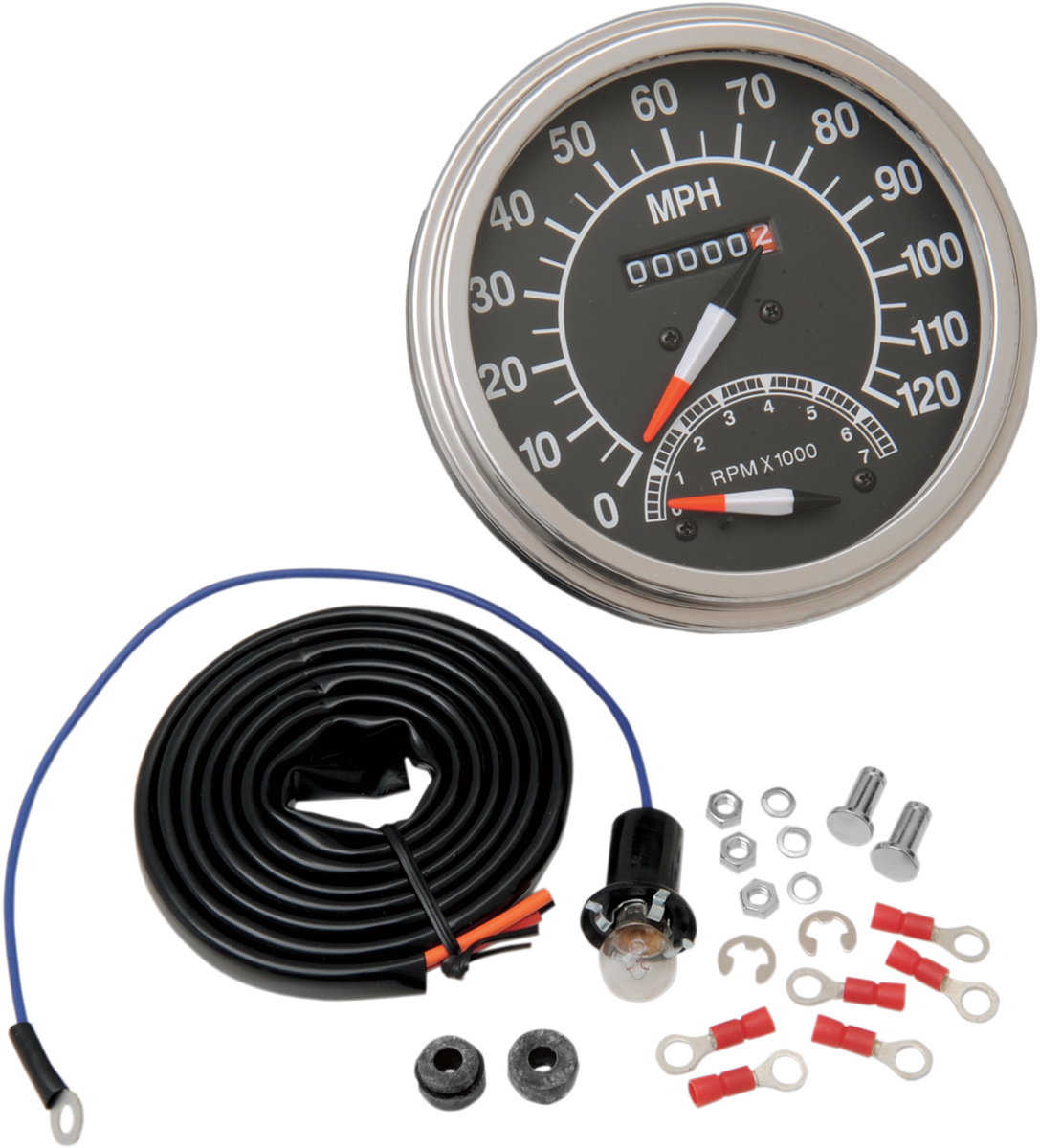
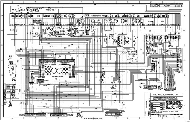
Attach the wire from pin 3 to a ground negative source. Discussion in the hokey ass message board started by newredporch apr 20 2013.
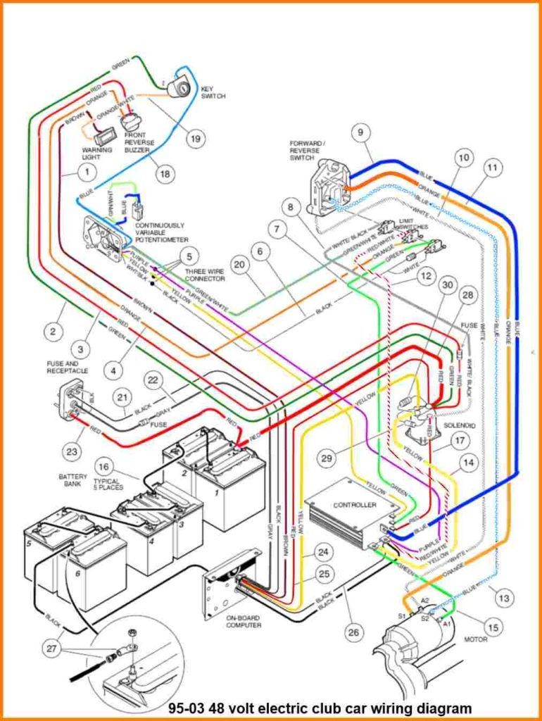
Ezgo Txt 48 Volt Wiring Diagram Wiringx Alpa Zografisch Nl
Medallion tachometer wiring diagram. For chrysler blue gold and silver boxes ford standard electronic ignitions and most other oem standard cd and electronic ignitions. A friend donated this tach to my project. Medallions viper ii helm instrumentation system delivers three innovative new technologies and capabilities to the marine industry including an panoramic 123 touch screen display simplified wiring via lvds for power and data transmission and the. The 4 setting makes it read approx. I am wondering if anyone can help with how to wire it. Refer to diagram d.
Sounded like bull so i set it to 4 under advice from a sf member. My tach was set at 3 when i bought the boat and it was telling me 7200 at 75 mph with 28 chopper. Use plug in connector kit pn 0174732 when installing tachometer only. Wiring connect the tachometer wires as shown. Safety and durability are our top priorities. 5700 at 70 mph same prop which sounds correct.
I dont want to fry it. Wire to a junction and attach the wire from pin 4 at this junction ie. Medallion partnered with malibu boats to win the coveted ibex innovation award at the annual conference held in tampa florida this year. Connect a wire from pin 5 to a constant 12 or 24 volt source. Creating the right solution for your application. 12v battery coil ignition coil tach base can be mounted in either direction for convenient mounting.
One such source can always be found where the battery is attached to the metal frame of the vehicle. Use a wiring kit to connect the tachometer to the plug in connector on the remote control or accessory electrical cable. Use plug infuse block kit pn 0173611 when installing tachometer with other accessories. Oct 8 2010 posts. Simplified user interaction design reduces driver distraction and improves safety by keeping critical information on the top level of the ui. White red black green grommet.
The wiring diagram shown is a typical installation.
