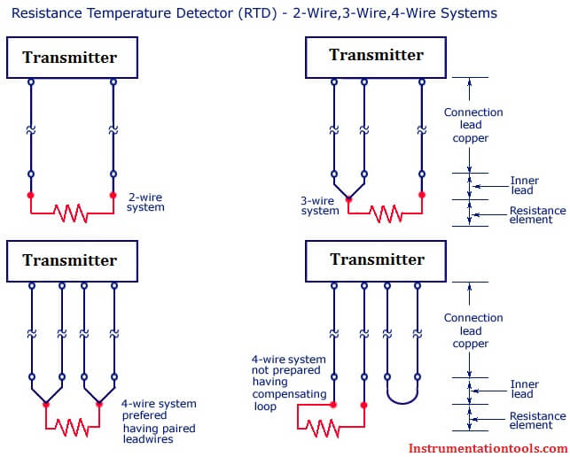
Bonded to the pt100pt1000 are 2 3 or 4 wires. Rtd wiring configurations there are three types of wire configurations 2 wire 3 wire and 4 wire that are commonly used in rtd sensing circuits.
3 Wire Rtd Sensor Wiring A 3 Wire Rtd 3 Wire Rtd Probe
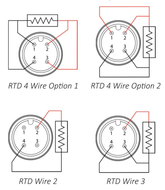
Rtd wiring diagram. The following connection diagrams illustrate how to connect various rtd types to your daq device. No current flows through it while the bridge is in balancesince l1 and l3 are in separate arms of the bridgeresistance is canceled. A1b1 a2b2 and c1c2. A 2 wire configuration with a compensating loop is also an option. 2 wire rtd wiring diagram. Eo is the output voltage.
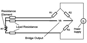
3 wire rtd wiring diagram in this circuit there are three leads coming from the rtd instead of two. Rtd wiring diagrams 2 wire circuit. In this uncompensatedcircuit lead resistance l1 and l2 add directly to rt. 2 lead constructions result in leadwire resistance getting added to the element resistance. Es is the supply voltage. A wiring diagram is a streamlined standard photographic depiction of an electrical circuit.
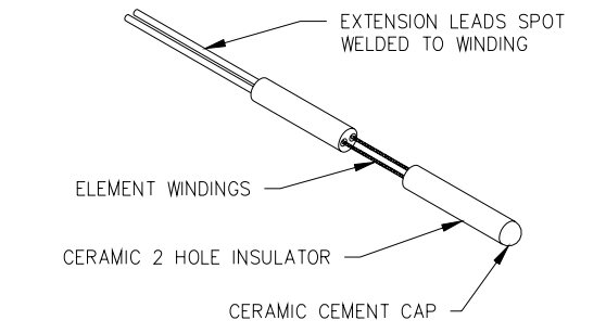
Consequently the temperature reading is artificially high. Es is the supply voltage. Just a small strip of platinum that measures 100 ω or 1000 ω exactly at 0 c. Shown is a 2 wire rtd connected to a typical wheatstone bridge circuit. And rt is the rtd. Shown is a 2 wire rtd connected to a typical wheatstone bridge circuit.
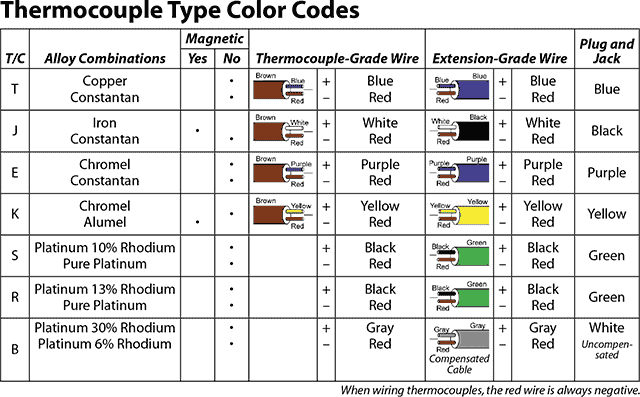
It shows the components of the circuit as streamlined shapes and also the power and also signal links between the gadgets. A wiring diagram is a simplified standard photographic representation of an electrical circuit. Connect the black or white lead on the negative side for the resistive. R1 r2 and r3 are fixed resistors. The graph below shows the temperature error from 2 leads of various sizes and lengths for a 100 ohm platinum rtd at 100c. It reveals the parts of the circuit as simplified forms and also the power and also signal links between the devices.
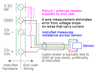
L1 and l3 carry the measuring current while l2 acts only as a potential lead. When wiring with two wires first jumper across a1 and b1and a2 and b2 respectively then connect pt100 sensors and to the rtd module according to the following diagram on the left. Rtd wiring config lady ada rtds are really very simple devices. 2 wire rtd connections the 2 wire rtd configuration is the simplest among rtd circuit designs. Assortment of rtd pt100 3 wire wiring diagram. 4 wire rtd signal connection connect each of the red leads on the positive side of the resistive element to the excitation positive and channel positive on the daq device.
L1 and l3 carry the measuring. A common version. There are 2 wiring methods for the rtd module and pt100 temperature sensors two wire and three wire connections. In this circuit there are three leads coming from the rtd instead of two. Collection of 3 wire rtd wiring diagram. December 12 2018 by larry a.
Gallery of Rtd Wiring Diagram