Rtd Transmitter Wiring Diagram

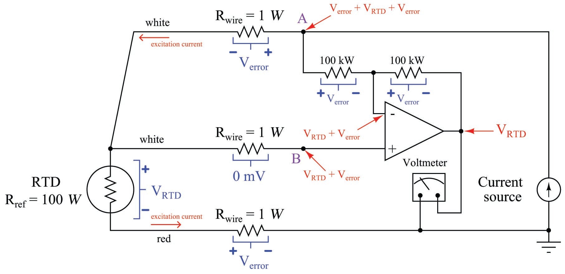
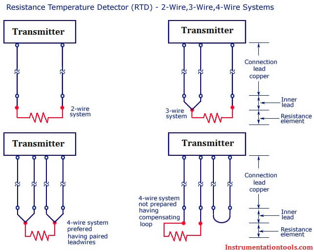
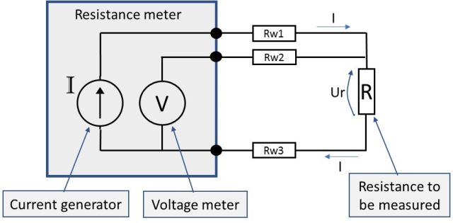
3 wire rtd connections the 3 wire rtd configuration is the most commonly used rtd circuit design and can be seen in industrial process and monitoring applications. Eo must have high impedance to prevent current flow in the potential leads.

What Is An Rtd Rtd Types Uses And More By Jms Southeast

What Is An Rtd Rtd Types Uses And More By Jms Southeast

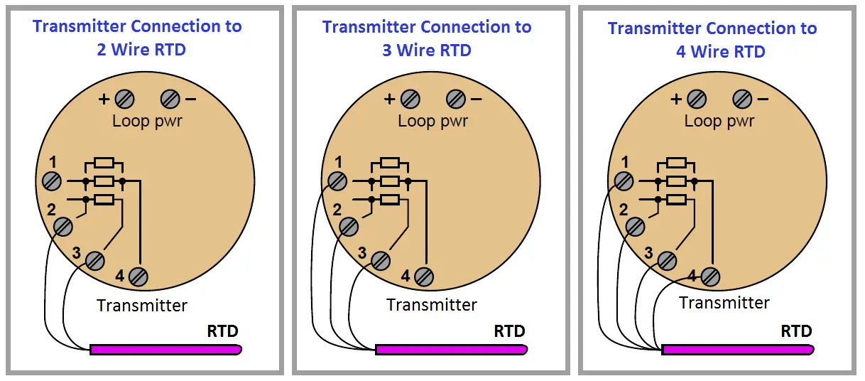
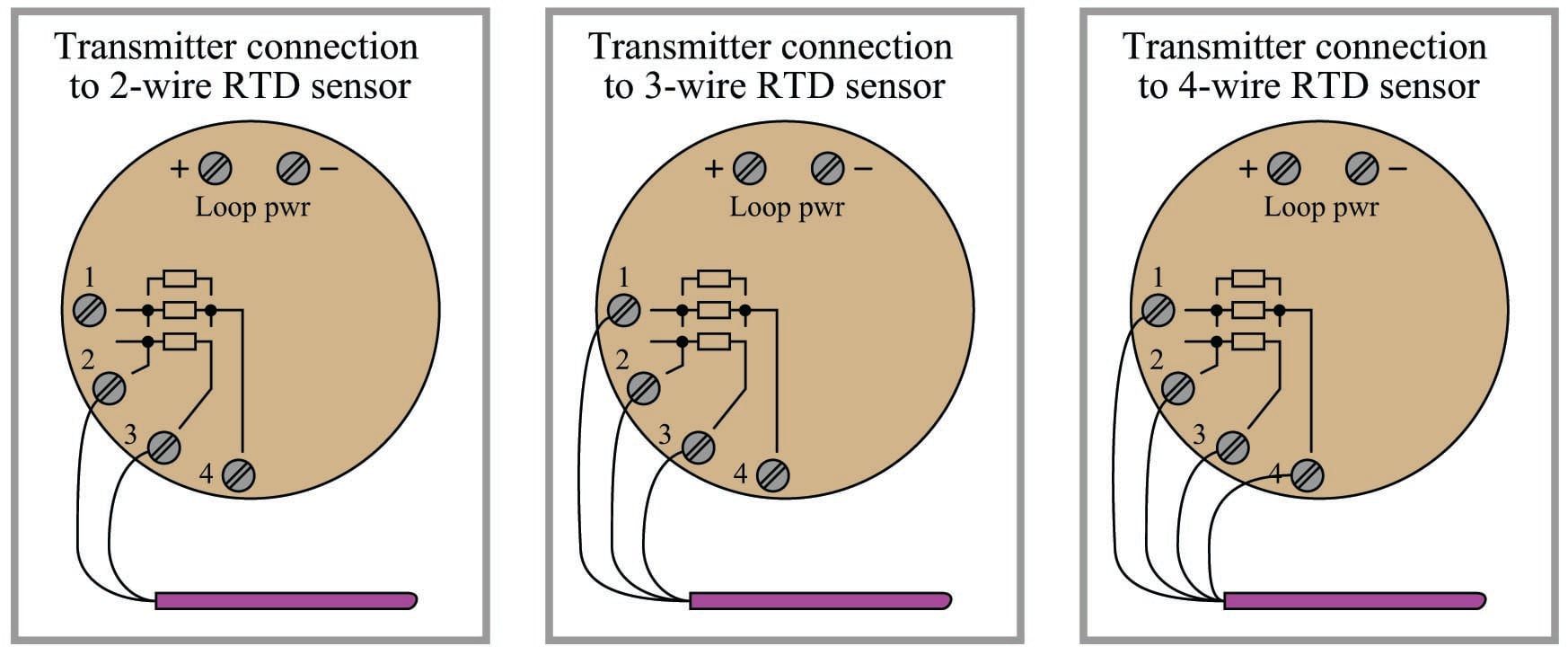
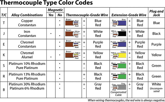
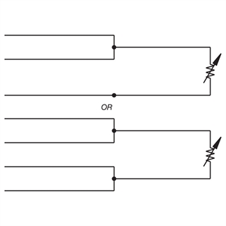
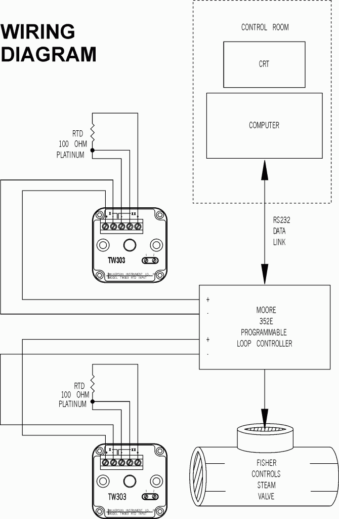
Rtd transmitter wiring diagram. 2 wiring diagram for rtds. Rtd lead wire configuration per iec 60751. A resistance temperature detector rtd is a temperature measurement device that accurately uses resistance to measure temperature. L2 and l3 measure the voltage drop across the rtd element. A 2 wire rtd configuration is the most useful with high resistance sensors or in applications where a great deal of accuracy is not required. When wiring with two wires first jumper across a1 and b1and a2 and b2 respectively then connect pt100 sensors and to the rtd module according to the following diagram on the left.

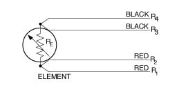
4 wire circuits may be usable over a longer distance than 3 wire but you should consider using a transmitter in electrically noisy environments. The following connection diagrams illustrate how to connect various rtd types to your daq device. Single element 3 wire single element 4 wire dual element 3 wire. 4 wire rtd signal connection connect each of the red leads on the positive side of the resistive element to the excitation positive and channel positive on the daq device. Connect the black or white lead on the negative side for the resistive. Learn the differences between 2 wire 3 wire and 4 wire rtds.

A1b1 a2b2 and c1c2. There are 2 wiring methods for the rtd module and pt100 temperature sensors two wire and three wire connections. Red red white white red red white red red white black black yellow. Note to configure a single element 4 wire rtd as a 3 wire system connect only one white lead. Is drives a precise measuring current through l1 and l4.

Gallery of Rtd Transmitter Wiring Diagram

Rtd Sensor Connections Instrumentation Tools
Download Now
Rtd Sensor Connections Instrumentation Tools
2 3 And 4 Wire Rtds What Is The Difference
Download Now
2 3 And 4 Wire Rtds What Is The Difference
Thermistors And Resistance Temperature Detectors Rtds
Download Now
Thermistors And Resistance Temperature Detectors Rtds
Download Now
Thermistors And Resistance Temperature Detectors Rtds
Which Temperature Sensor Do I Need An Rtd Or A Thermocouple
Download Now
Which Temperature Sensor Do I Need An Rtd Or A Thermocouple
Rtd Sensor Ohmic Signal Conditioning Interfacing Diagram
Download Now
Rtd Sensor Ohmic Signal Conditioning Interfacing Diagram
Bg 8994 Pt100 Rtd Wiring Free Diagram
Download Now
Bg 8994 Pt100 Rtd Wiring Free Diagram
Difference Between 2 Wire Rtd 3 Wire Rtd And 4 Wire Rtd S
Download Now
Difference Between 2 Wire Rtd 3 Wire Rtd And 4 Wire Rtd S
Rtd Wiring Diagrams
Download Now
Rtd Wiring Diagrams
Rtd Temperature Transmitter
Download Now
Rtd Temperature Transmitter
Wilkerson Instrument Company Inc Blog Rtd
Download Now
Wilkerson Instrument Company Inc Blog Rtd
Xm 3246 2 Wire Rtd Wiring Diagram Wiring Diagram
Download Now
Xm 3246 2 Wire Rtd Wiring Diagram Wiring Diagram
Rtd Amplifier Circuit Measuring Rtds Connecting Rtd To
Download Now
Rtd Amplifier Circuit Measuring Rtds Connecting Rtd To
2 3 And 4 Wire Rtds What Is The Difference
Download Now
2 3 And 4 Wire Rtds What Is The Difference
Active Versus Passive Temperature Sensors Digikey
Download Now
Active Versus Passive Temperature Sensors Digikey
Resistance Measurement 2 3 Or 4 Wire Connection How Does
Download Now
Resistance Measurement 2 3 Or 4 Wire Connection How Does
Rtd Sensors Evolution Sensors And Controls
Download Now
Rtd Sensors Evolution Sensors And Controls
Rtd Sensor Ohmic Signal Conditioning Interfacing Diagram
Download Now
Rtd Sensor Ohmic Signal Conditioning Interfacing Diagram
Resistance Thermometer Wikipedia
Download Now
Resistance Thermometer Wikipedia