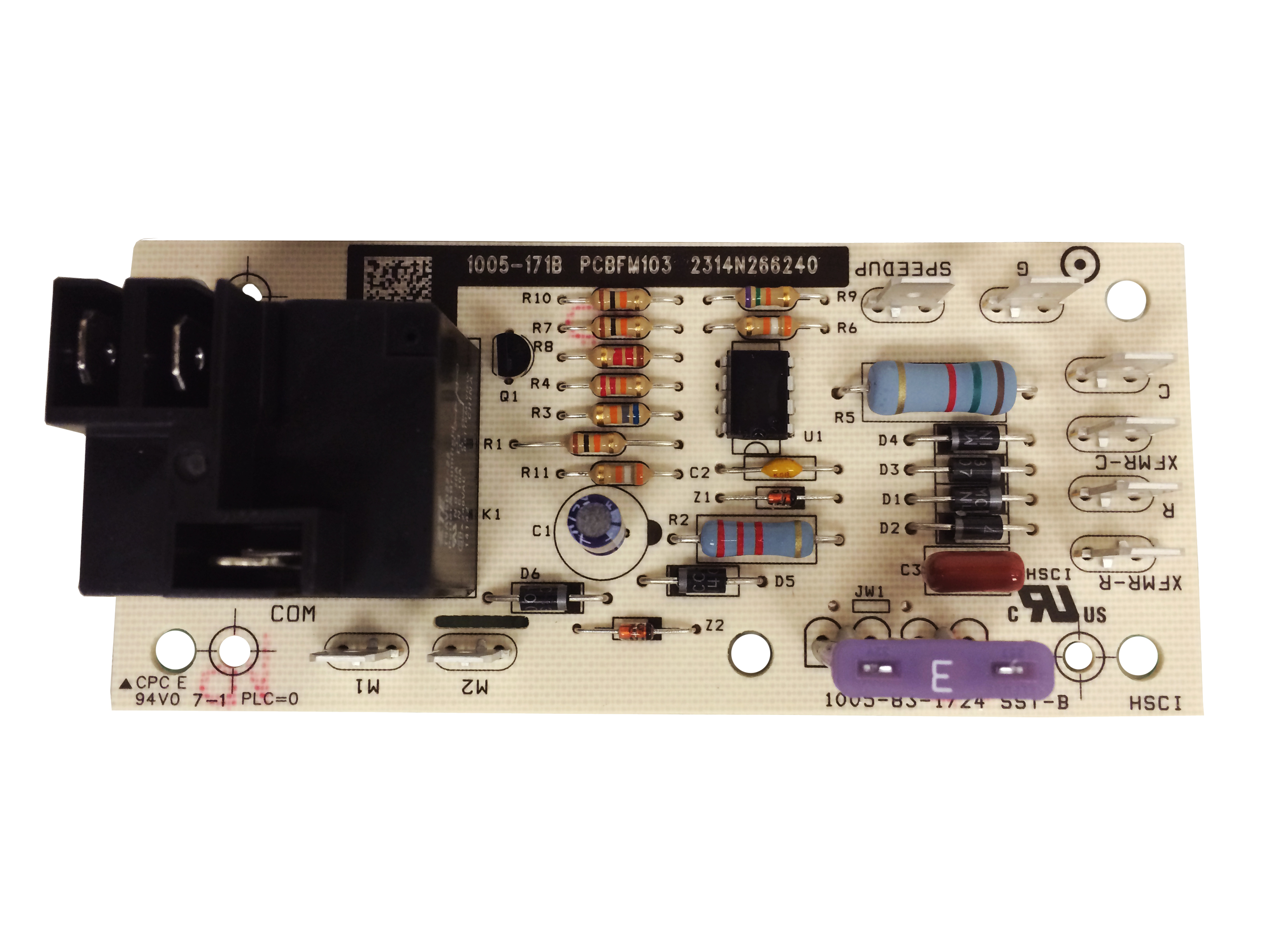
Control board rewire pcbfm103 answered by a verified hvac technician. We use cookies to give you the best possible experience on our website.

Read Or Download Dormitory Security Wiring Diagram For Free
Pcbfm131 wiring diagram. To see if your model number is in this list hold down the ctrl key and press f then put your model number in the. All of our parts are. Wiring diagram for a 2ton goodman closet unit. Heat pump repair when your heat pump has failed call the heating experts in the triangle expert express. If youd like to support the channel you can do so by shopping for whatever you need on amazon through this link httpamznto2a82m7z check out my websit. Wiring harness 1 thermal well 2 thermostats 4 gas connectors 6 installation kits 1 gas thermostats 9 drain valves 6 pilot burner assemblies 3 temperature.
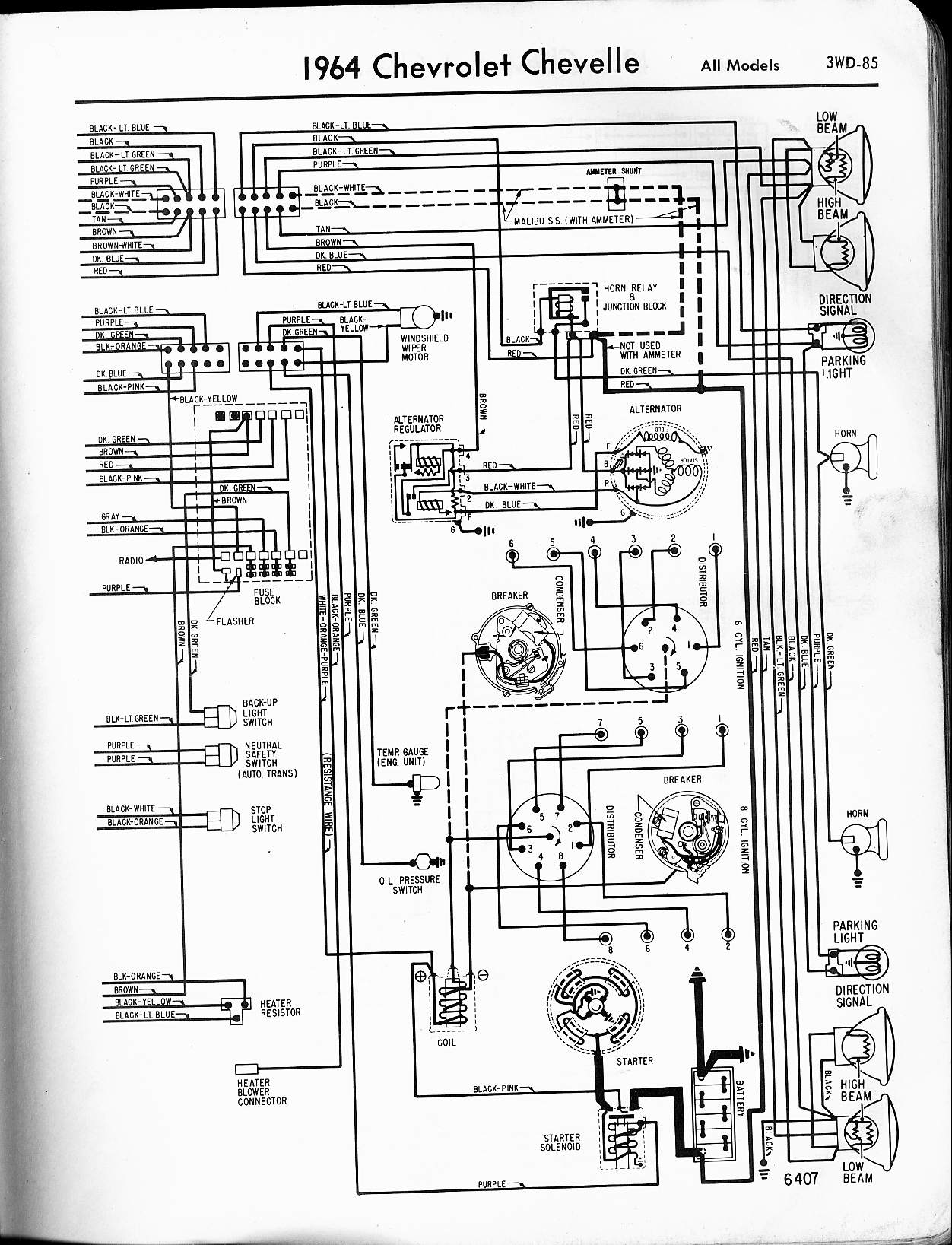
151 pcbfm131 wire assy 9 pin female connector m1 m2 m3 m4 171 0259a00001p wire assy 9 pin female connector m5 m6 m7 m8 m9 m10 m11 m12 m13 m14 m15 m16 m17 m18 m19 m20 m21 171 0259a00005p 181 0259a00002p wire assy 9 pin male connector 201 0154a00000bl drain pan gasket qty 2 plastic drain pan horizontal m1 m2 m3. 1 wiring diagram model sizes 1 12 5 tons 208230 1. A wiring diagram typically gives information concerning the relative placement and also plan of devices as well as terminals on the gadgets to assist in structure or servicing the device. Pcbfm131 blower control 4100 this part is used on these model numbers. Our technicians are highly experienced servicing. By continuing to use this site you consent to the use of cookies on your device as described in our cookie policy unless you have disabled them.
Fan blower control replacement for goodman b1370735s pcbfm131s control boards. Wiring diagram for a trane air handlwr twe036p13fao. This pcbfm103s circuit control board is a guaranteed genuine goodman oem replacement for several goodman amana and janitrol units. Samsung rf323tedbsr parts diagram. 2 rvs dts yel pnk speed up brnyel dft c y o w2 r e l g terminal block indoor unit red wht orn yel blk cb c y o w2 r e l w3 g blu pnk yelblu yelblu hps lps logic logic t2 cont c ctd t1 c y y dft dft rvs c r w2 o o schematic diagram ladder form. This differs a schematic layout where the plan of the parts interconnections on the layout normally does not match to the components physical.
Gallery of Pcbfm131 Wiring Diagram