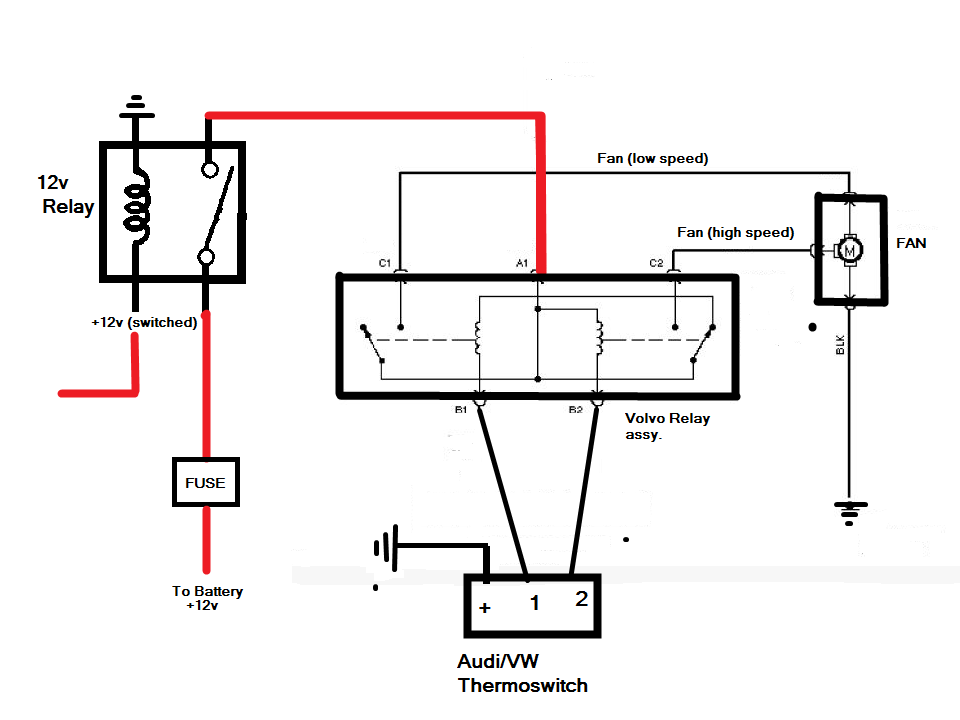
Assortment of mishimoto fan controller wiring diagram. Interconnecting cord paths may be revealed about where certain receptacles or components have to get on a common circuit.
Universal Radiator Fan Wiring
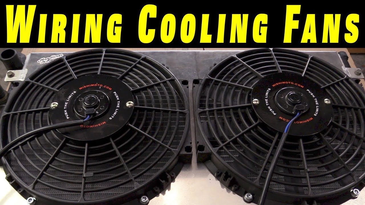
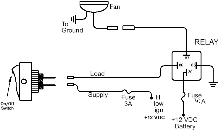
Mishimoto fan wiring diagram. Mishimoto fan controller wiring diagram architectural circuitry layouts reveal the approximate areas and also affiliations of receptacles illumination as well as irreversible electrical solutions in a structure. The experts at mishimoto have created this instructional how to wire a fan do it yourself video guide to help you every step of the way. Plug the wire harness into the fan control module. It reveals the parts of the circuit as streamlined forms and the power and signal links between the tools. Using the electrical connectors and wire ties provided follow the instructions below. It reveals the elements of the circuit as simplified forms as well as the power and signal connections in between the tools.
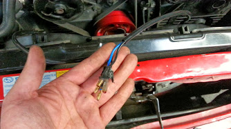
Positive battery to positive fan lead 4. This controller includes a built in ac override feature and is designed for use with 12 electric fans drawing a combined 25 amps or less. The mishimoto fan controller features adjustable activation from 150f to 240f and deactivates once temperatures are reduced by 10f. Variety of mishimoto fan controller wiring diagram. See diagram 4 on third page 3. A wiring diagram is a simplified standard photographic depiction of an electrical circuit.
Using the blue 516 ring terminal provided attach one end of the. A wiring diagram is a simplified conventional pictorial representation of an electric circuit. Make sure to check out some of other do it yourself videos to keep your ride out of the shop and out on the track.
Gallery of Mishimoto Fan Wiring Diagram