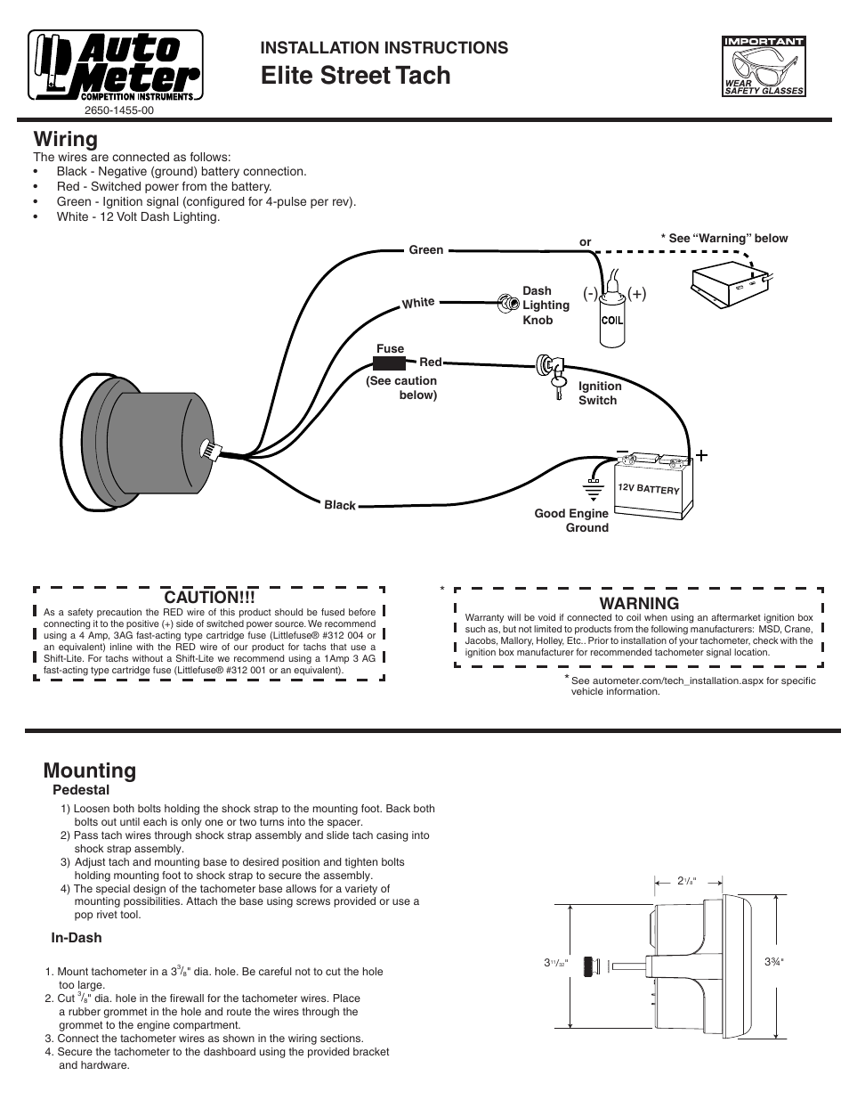
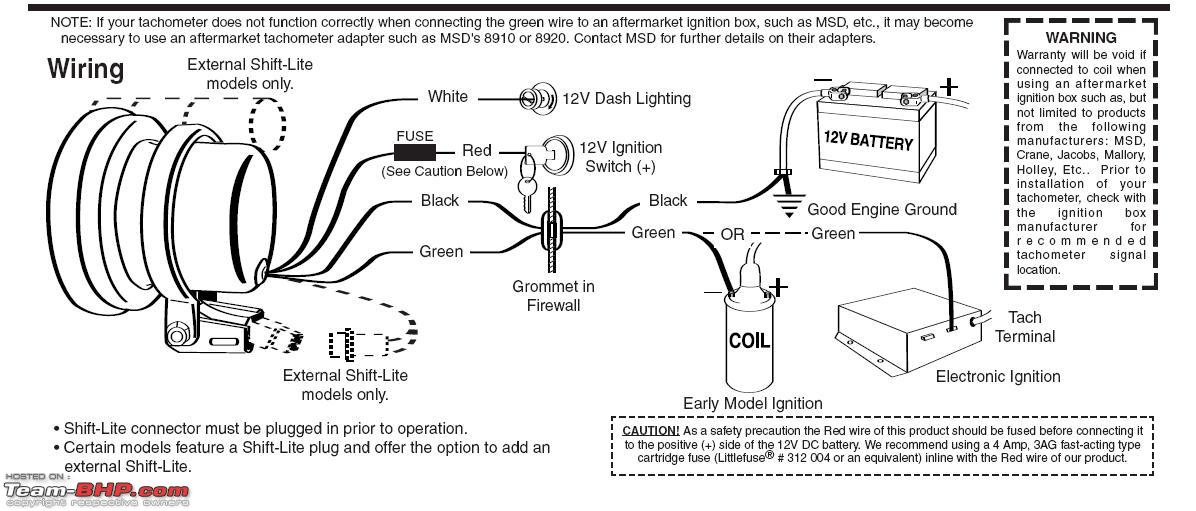
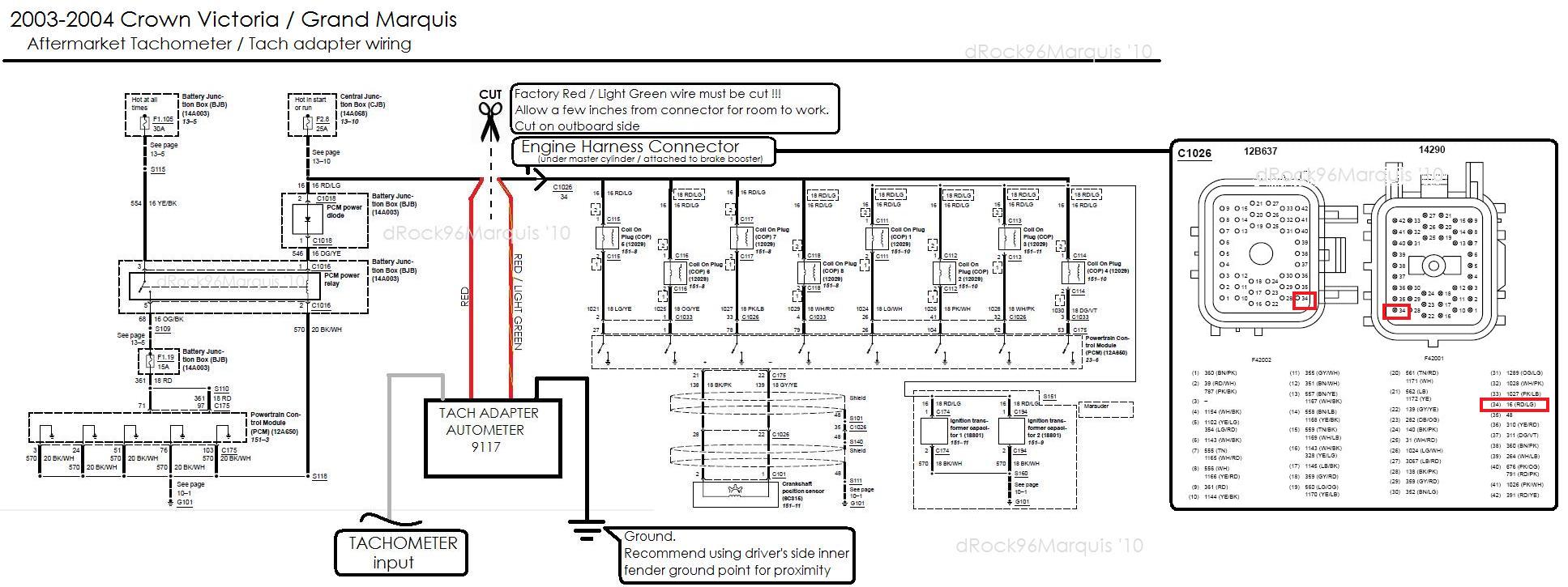
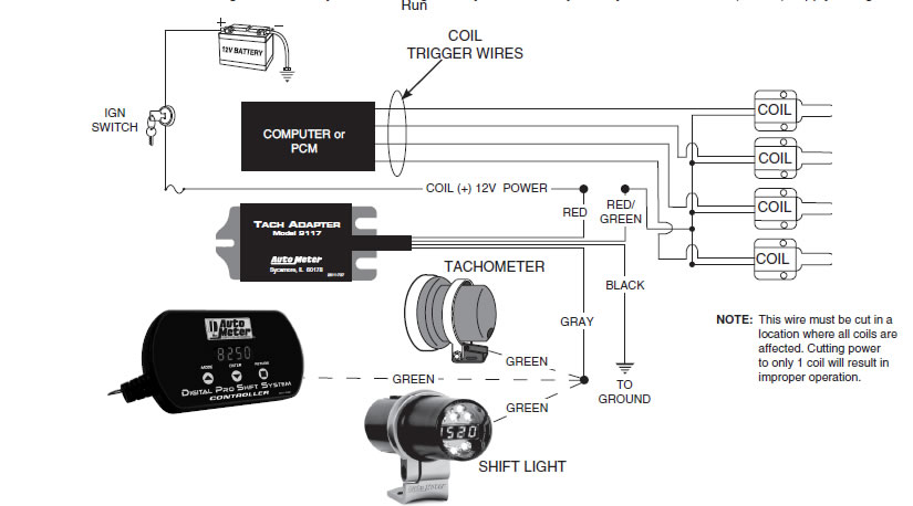
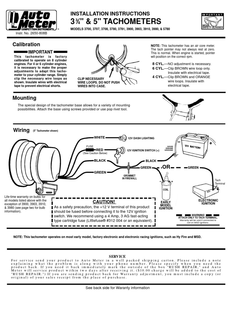
Autometer tach wiring diagram auto meter tach wiring diagram at autometer autometer tach wiring diagram. Wiring your new autometer tachometer into your car will complete the installation.

Gr 2905 Comp Auto Meter Tach Wiring Diagram On Autometer
Autometer tach wiring diagram. Click on the image to enlarge and then save it to your computer by right clicking on the image. Once you have selected a mounting location you can run the four wires that operate the tachometer. Auto gauge tach wiring wiring diagram data autometer gauge wiring diagram wiring diagram consists of numerous in depth illustrations that show the connection of varied items. The tachometer is designed to show the engine rpms or rotations per minute. With power off it is normal for the pointer to leave zero. The wiring diagram shown is a typical installation.
This tachometer has an air core meter. For chrysler blue gold and silver boxes ford standard electronic ignitions and most other oem standard cd and electronic ignitions. Wiring connect the tachometer wires as shown. 5 tachometer 2650 1244 00 rev. Autometer has designed their tach to be used with four six. When 12v power is applied.
It contains directions and diagrams for various varieties of wiring strategies along with other things like lights windows etc. If after completely reading these instructions you have questions regarding the operation or installation of your instruments please contact auto meter technical service at 866 248 6357. 5 tachometer part number p5155500 p5155975 introduction any auto meter shift lite or quick lite shift lite can be used with tachs equipped with a black shift lite connector. Variety of autometer tach wiring diagram.


