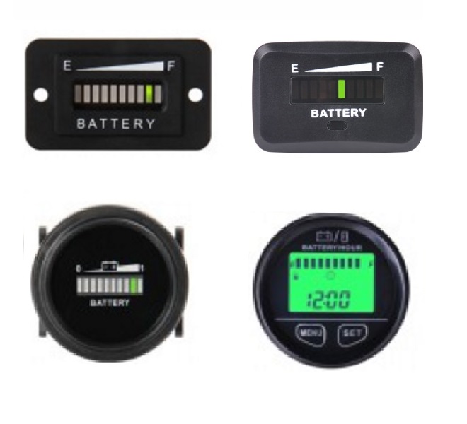
Void of moving parts this combination instrument is exceptionally reliable even in severe operating environments. Battery fuel gauge 16 pages measuring instruments curtis acuity 1030 manual.
Forklift Parts 803 Curtis Battery Discharger For Electric
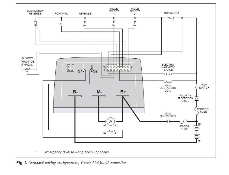
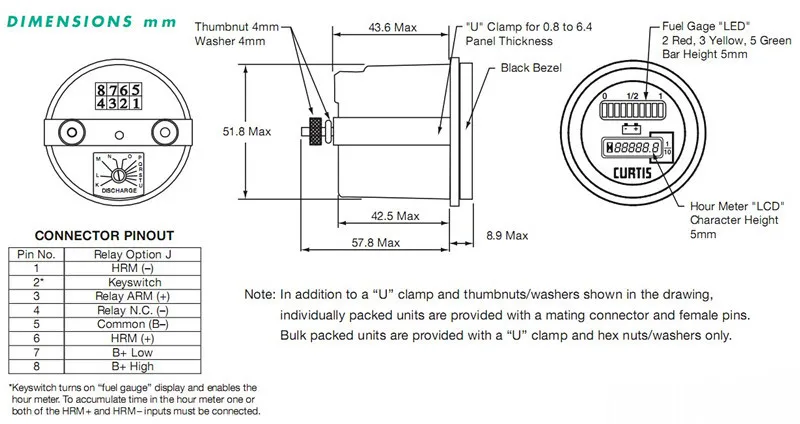
Curtis battery meter wiring diagram. Pin 1 battery connects to the vehicles main positive terminal. Sequential logo code 00 2 wire hour meter see section 22 r electrical reset o curtis 01 3 wire hour meter for specifications n no reset n no logo 03 pulse counter xxyy nominal voltage see section 21 for. Curtis battery meter wiring diagram 21032011 does any body have a wiring diagram for the battery meter mine is a curtis brand and i think mine is hocked up wrong what its doing is after i get. Advanced technology for evs. Curtis instruments wiring diagrams together with 1126890 65 ford f100 wiring diagrams further 79gwx need find info electrical schematic john deere 345. Golf cart batteries are wired in series with the positive terminal of each battery linked to the negative terminal of the next one.
Pin 2 battery connects to the vehicles main negative terminal use as short a wire as practical. Next step will be to connect the wire to the signal terminal on the meter to the ignition. Installing a battery monitoring voltage meter is a useful project requiring only basic wiring skills and the ability to use simple tools. Assortment of golf cart battery meter wiring diagram. A wiring diagram is a streamlined standard pictorial representation of an electric circuit. You will need to add a jumper from the ignition on off switch to the tab on the bottom of the battery gauge which is a signal wire.
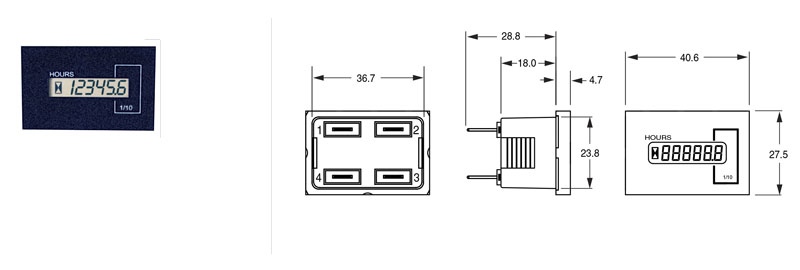
Leaving pin 1 open or connecting it to high voltage gives control of the hour meter to the hour meter input2 3 0 pin 3 connects in series with the lift coil circuit or the circuit to be switched at empty. Use as short a wire as practical. Instrumentation motor speed controllers inverters integrated systems drive systems and engineering support for electric vehicle designers. Table 1 to activate the hour meter. For holding relay j pin 3 must be electrically closer to battery than pin 42 4 0. It reveals the elements of the circuit as simplified shapes and also the power and signal connections between the devices.
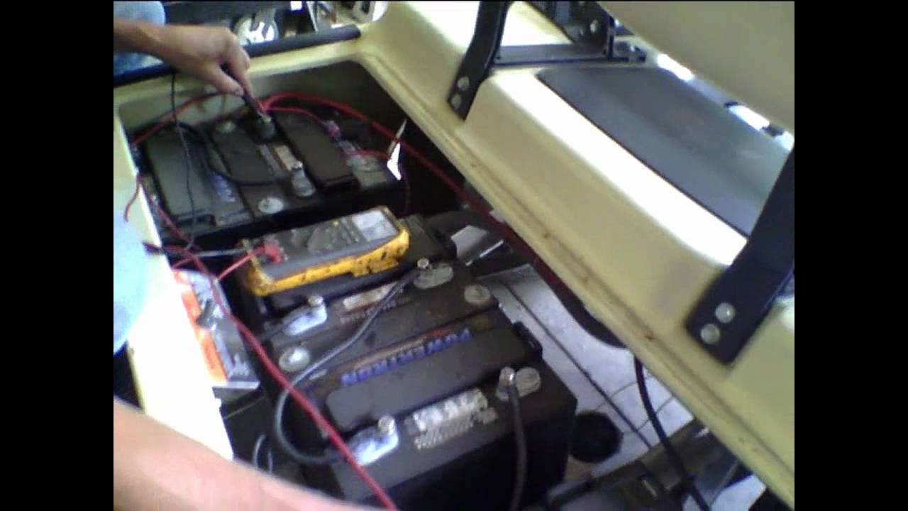
Locate the battery tray and examine the batteries. Battery monitoring system 31 pages. This way the meter only comes on when you turn the golf carts ignition on. Curtis model 803 combines in one instrument a completely solid state battery discharge indicator an lcd hour meter and lift lockout housed in a 52mm case. Pins 1 2 are connected across the total battery pack.
Gallery of Curtis Battery Meter Wiring Diagram