The 7 way smart bypass relay does the job of translating these signals and is a simple in line fit between the towbar wiring and the vehicle loom. Relay logic is all about wiring up relays for logical switching applications.

Diagram Based Rover 25 Towbar Wiring Diagram Completed
Rct485 smart logic relay wiring diagram. In above block diagram there is coil which consist two terminal a1 and a2. All examples shown are for spdt single pole double throw relays which includes any of the 5 10 or 20 amp relays on this site. Diagrams will show how multiple relays one relay or another or just one relay can control your device. Relay logic provides you with a guide for using ncd relay controllers and how they can be wired for many types of applications. Relay is an electromechanical device which operates by current. How the relay works.
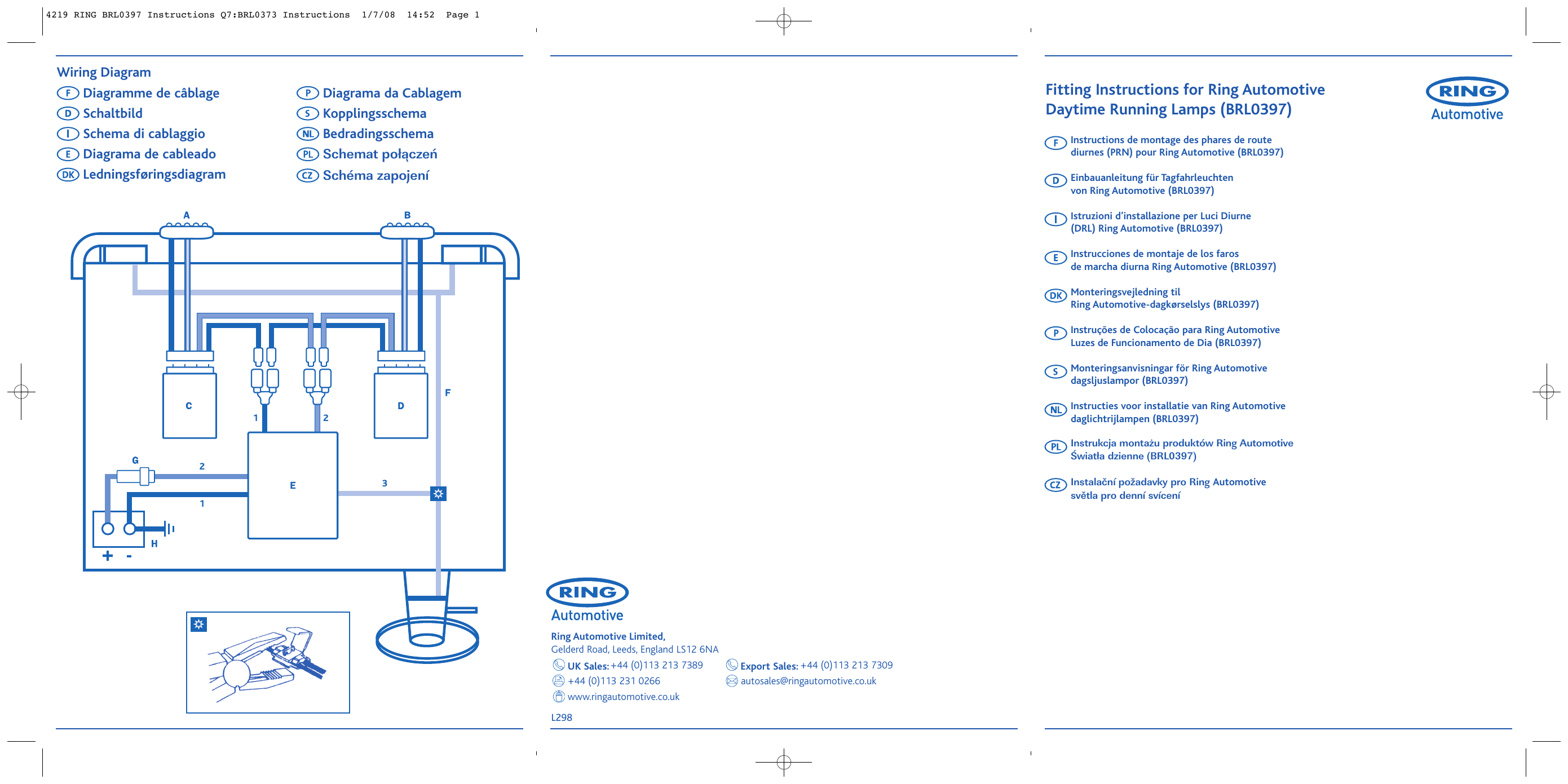
Ground wires greenwhite to pin 13 bluewhite to pin 11 white to pin 3. Smart7 bypass relay with pluggable loom for the connections to the vehicle the tf22187h tf22187hs and tf22187hm replace every previous 7 way bypass from tf1016 to tf22187e p including tf2219 tf2218u etc. Tec3m terminals 2 no connection 4 to pin 9 6 to pin 10 of the towbar plug. The fitter need not have an in depth understanding of the multiplexed system the smart bypass relays inbuilt microchip does all that. Rct485 smart logic relay ring automotive limited gelderd road leeds england ls12 6na tel. Fitting is very straightforward.
Smart logic bypass with plug in loom 1000mm. This page demonstrates several simple ways to wire a relay for various applications. Switches the caravan auxiliary circuits on when the vehicle alternator provides sufficient power fuse rating. 44 0113 231 0266. The smart logic relay comes complete with a built in indicator warning buzzer an audible warning device is mandatory by law. After few year relay become use for different purpose and application.
Basically a relay will be a rectangular block with at least 4 electrical connectors exposed. The relaymay also be referred to as canbus multiplex or smart. Relays come in several form factors. Rct465 smart combi relay function. With this brief introduction out of the way lets start talking about how to use relays in your projects. Relay consists one coil armature spring and contact as shown in images.
Basic diagram of relay images. 20 amps socket pin number 7 pin13 pin 7 core cable colour to relay pin vehicle circuit 18 210 311 49 5spare 610 713 yellow blue. 44 0113 231 0266 fax. Wiring the 12s or 13 pin socket connecting to the vehicle. Ryder smart logic 7 way bypass relay tf22187h for can bus multi plex wiring 1899 ring rct360 12s combination split charge relay kit for charging battery fridge. This page demonstrates several simple ways to wire a relay for various applications.


