Wiring diagram number quotation number. Selected wiring diagrams under documents attention.
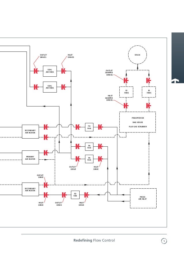
Wrg 5324 Auma Valve Wiring Diagrams
Auma valve wiring diagram. Mounting to valve gearbox 12 7. Y001931002en proposed wiring diagram for sa with 3 phase ac motor asv1111111 kmstp110001 issue 108 we reserve the right to alter data according to improvements made. Mounting positions of the local controls 14 8. Feedback indications from actuator and valve 20 422. Order data sheet. Electrical connection 15 81 connection with auma plug socket connector s sh se 17 9.
The wiring diagram opens in a pop up window. Change colour 26 5. Transport storage and packaging 10 51 transport 10 52 storage 10 53 packaging 11 6. Additional information to the wiring diagram legend 9 5. Wiring diagram for standard version multi turn actuator closes valve clockwise. Tools pop up blocker pop up blocker settings.
The wiring diagram opens in a pop up windowif the pop up blocker is turned on in your browser you are not able to view the wiring diagram. Status indications according to namur recommendation 24 43. The component automatically switches the actuator off once the valve end position is reached motor overheating is detected or a torque overload has occurred. Auma riester gmbh co. Please enter the address of our website in the address of web site to allow box. Manual operation 19 10.
If the pop up blocker is turned on in your browser you are not able to view the wiring diagram. 1 d 79379 muellheim. The wiring diagram shows the non rotating multi turn actuator in intermediate position. Status indications according to auma classification 23 423. Please enter the address of our website in the address of web site to allow box. Interface to the dcs.
Indication lights of local controls 25 431.
Gallery of Auma Valve Wiring Diagram