Generator synchronizing panel wiring diagram disclaimer. For many years the researchers have paid great attention to develop the high performance synchronizing device 3.

Synchronizing
Synchronising panel wiring diagram. This synchronization panels are monitored often during the low demand of loads and during that time the one or or more generators will be automatically shutdown during that period to save the fuel consumpton. In many cases the process is automated using an automatic synchronizer with manual control available as a. 200300400 series wiring diagram pts8csi nm diesel wiring diagram powertech diesel wiring diagram powertech with ecu 63 control module wiring diagram. Propak12 and propak16 wiring diagram. We would like to show you a description here but the site wont allow us. Basics 8 aov elementary block diagram.
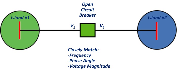
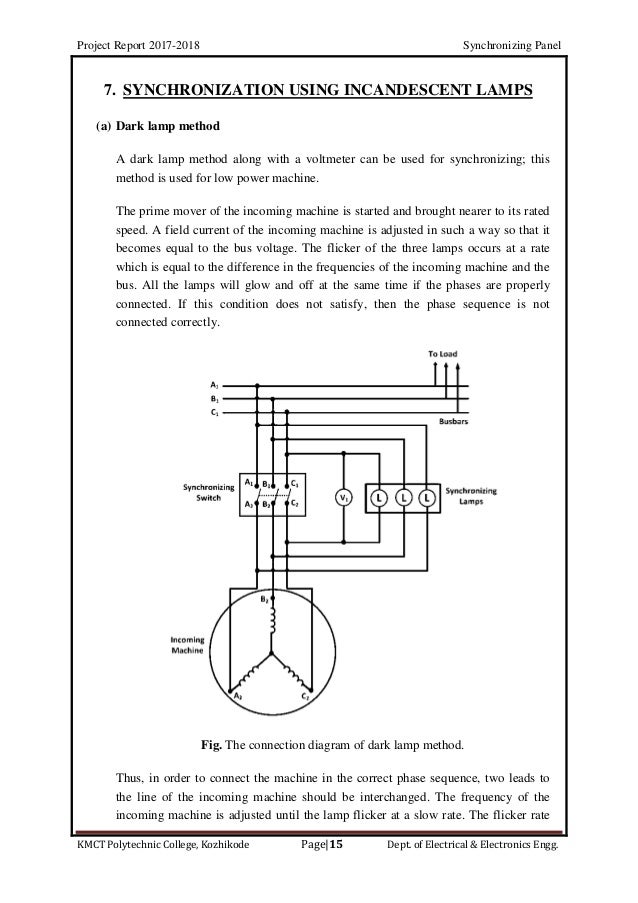
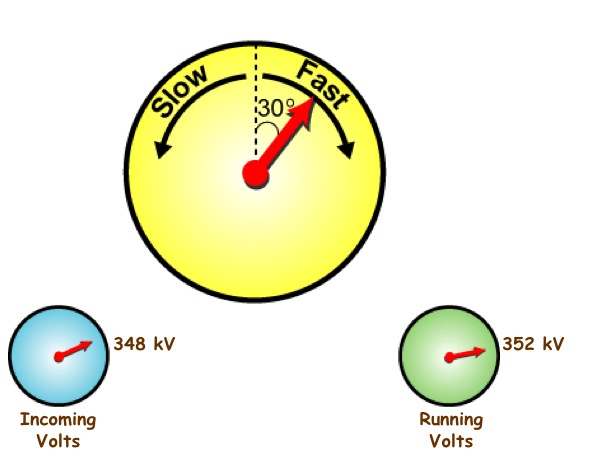
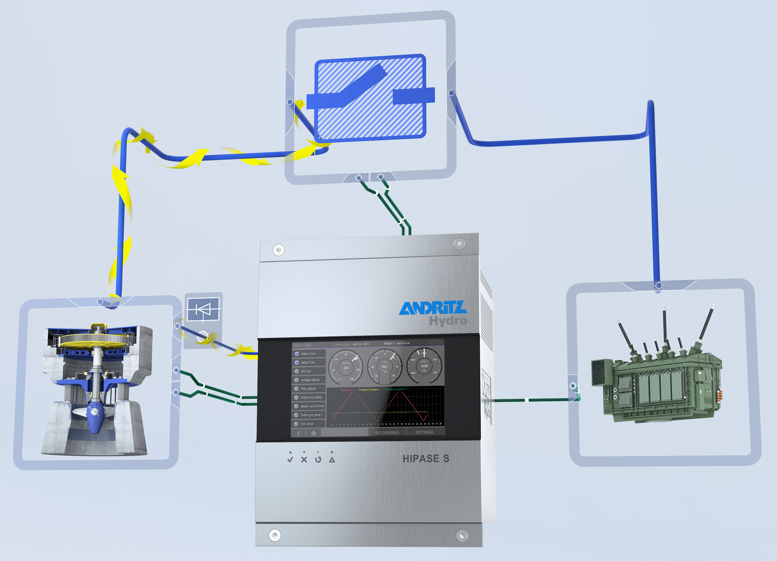
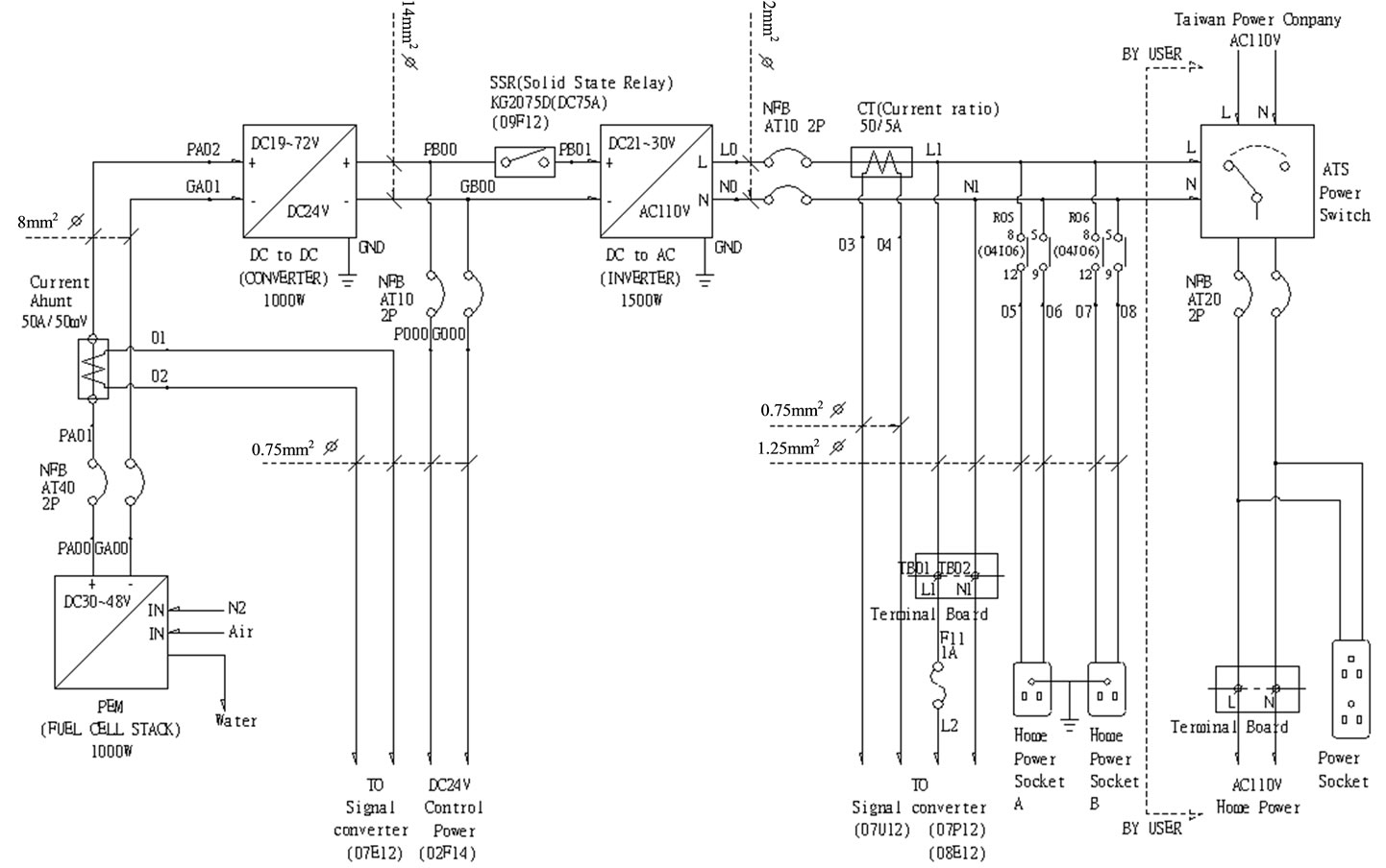
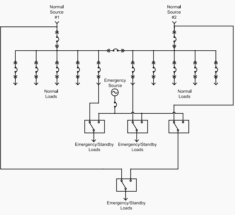
The synchronizing panel includes indications of voltage angle and slip that show what adjustments the operator needs to make to the governor and exciter and when it is acceptable for the operator to close the breaker. Basics 11 mov schematic with block included basics 12 12 208 vac panel diagram. Electrical wiring diagram synchronizing generator to grid panel wiring. Electrical wiring diagramsand problem. Basics 13 valve limit switch legend. The wiring diagram for connecting thee phase motor to the supply along with control wiring is shown in figure below.
Therefore the automatic synchronizing device plays an important role in the generator synchronizing. Gps 5600a wiring. We never admit that the image is our image the copyright is in the image owner we only help our users to find the information they are looking for quickly. The contactor contains large load contacts that are intend to handle large amount of current. Basics 7 416 kv 3 line diagram. The main problems of connecting a synchronous generator to an electrical system.
62249 phone 6186542341 fax 618654 2351 applications page 2 specifications pages 4 6 connections page 7 ordering information page 8 ubp 5 www 1 01. Basics 9 416 kv pump schematic. This is a start stop push button control schematic which includes contactor m overload relay control transformer and push buttons. Basics 10 480 v pump schematic. Box 269 highland illinois usa. If you want the image to be deleted please contact us we will delete it from our website.
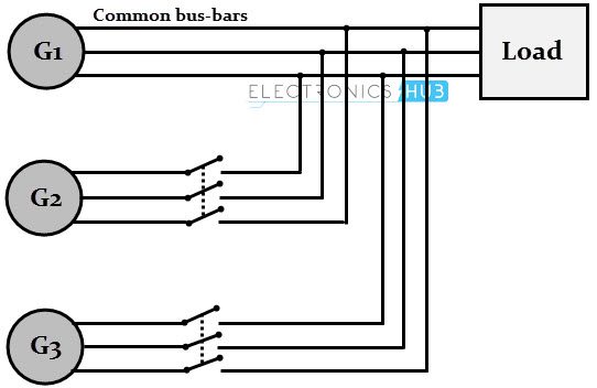
Need wireing diagrams for brake lights for 2003 f450 cube van. C13n6h c17n6h c20n6h and c20n6hc models wiring diagram hdkat hdkau and hdkav wiring diagram. When the demand rises again another generator will be resume and synchronized to the loads. Basics 14 aov schematic with block included basics 15 wiring or connection.

