Then voltammeter shows the volts and amperes. In this video we will look at a 3 combination voltammeter.

Mini Dc 100v 10a Digital Voltmeter Ammeter Blue Red Led
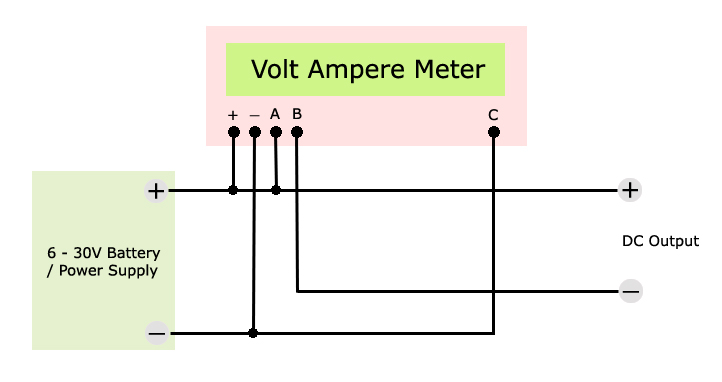
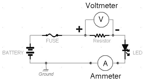
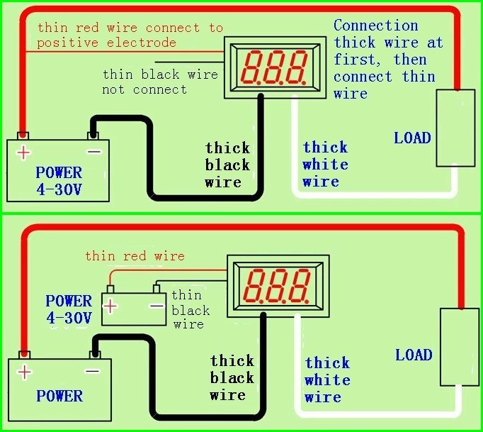
Digital volt amp meter wiring diagram. The thicker red black blue are connected the following way. In the diagram above the wire colours shown in brackets refer to model tc0002. Sr electric 50814 views. Sr electric 50626 views. A wiring diagram is a simplified traditional photographic representation of an electric circuit. It reveals the elements of the circuit as simplified forms and the power and signal connections between the devices.
How to use 0 100v 0 10a mini digital volt amp meter duration. We will also measure its accuracy and take readings and talk about the results. How to use 0 100v 0 10a mini digital volt amp meter duration. Kasyan tv 191775 views. In the article digital volt amp meter circuit diagram we are going to learn how how to make a digital volt amp meter. It reveals the parts of the circuit as simplified shapes as well as the power and signal links between the tools.
As you can see from the diagram both modules have 5 wire leads 2 for connection to meter power which must be in the range of 45 to 30v 2 for connection to the current shunt measuring terminals and 1 for the voltage measuring wire. Chris craft 67405 views. These guidelines will be easy to understand and apply. Volt amp meter wiring diagram for led wiring library digital volt amp meter wiring diagram. A wiring diagram is a streamlined traditional pictorial representation of an electric circuit. Assortment of volt amp meter wiring diagram.
Digital volt amp meter circuit diagram the circuit uses a single pic microchip to perform the voltage current temperature conversions display functions. Wiring diagram comes with numerous easy to adhere to wiring diagram guidelines. The way i had it setup for the past 3 weeks was thinner two wires red black to my 22ah battery. I have an ampvolt meter just like the one you have in this tutorial. Black is connected to the source 12v battery. Its meant to help all the average person in developing a suitable program.
Adjustable power supply from computer atx. A wiring diagram is a simple two power wire i connect to phase and groundafter connect this two wires voltammeter is turn on but measuring only voltageif i will measuring current i muss pass through the toroid one phase wire. Red is connected to the source 12v battery. After going phase wire through the toroid i plug load. We will go over how to exactly wire it and use it. How to wire ammeter and volt meter amp meter diy duration.
Collection of digital volt amp meter wiring diagram.


