Tsl 028 6 pl 150 120 331 363 mounting diagram height. R1510l or other acuregulator wiring diagram bat alt field bus alt out o v r f d alt red yellow black 40a 100a red black blue diode is pipers e regulator is between the.

1968 Mg Midget Wiring Diagram Auto Electrical Wiring Diagram
Zeftronics voltage regulator wiring diagram. 110 zeftronics electrical charging systems solutions. If the bus voltage exceeds the preset over voltage ov limit the ov relay which is normally closed will open. The voltage regulator with pulse width modulated pwm field control keeps the bus voltage constant by controlling the alternators field current. The voltage regulator keeps the bus voltage constant by controlling the alternators. With the relay off the controller and the alternator turn off to protect sensitive avionics equipment and the battery. Figure 3 shows the system with the r15v00 rev a installed as a replacement for both units.
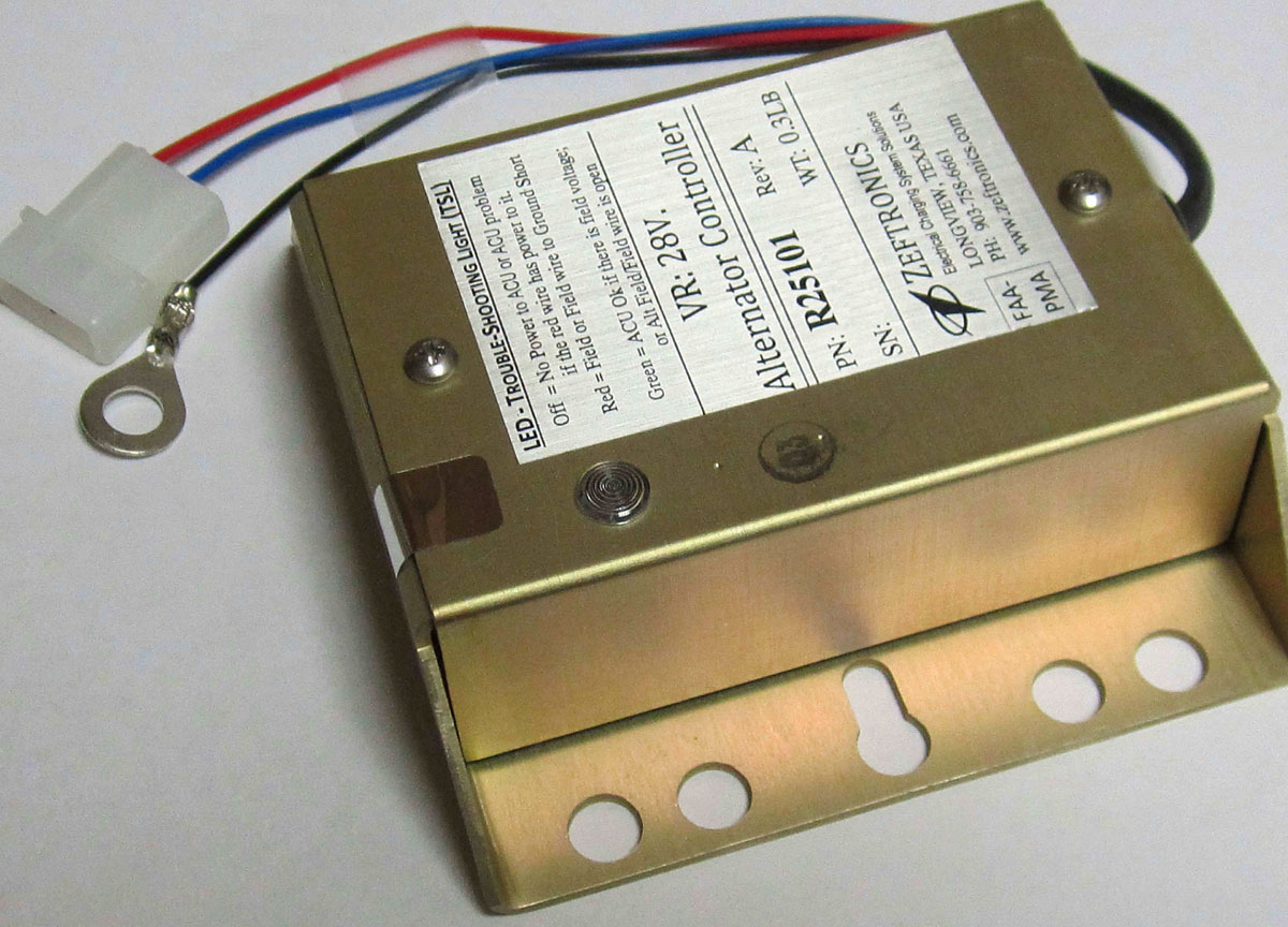
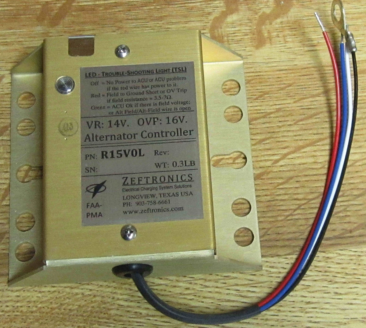
Ibitayo 2003 zeftronics tovya group inc r15v0l pitpub. Voltage regulation pulse width modulated. Off with the master switch on and no power to the acu red wire means that one power input device like switch circuit breaker or wiring is open. If the bus voltage exceeds the preset over voltage ov limit the ov normally closed relay will open up and. Pg 14 wiring diagram bat alt field bus alt out acu f1 alt f2 40a 100a red white blue black diode is used on pipers 5a bat relay ov gfp trouble shooting light continued. Reduced panel light flicker 022 2 pl.
110 by femi g. Figures 1 and 2 are setup in the standard cessna wiring configuration where the voltage regulator alternator controller and the overvoltage sensor are separate. Low over voltage sensor indication improves safetywarns of low voltage ov condition remote voltage sensing improved voltage regulation. Dgr6 ford pn. Reduced panel lights flicker. Expect the breaker to protect their non zeftronics regula tor.
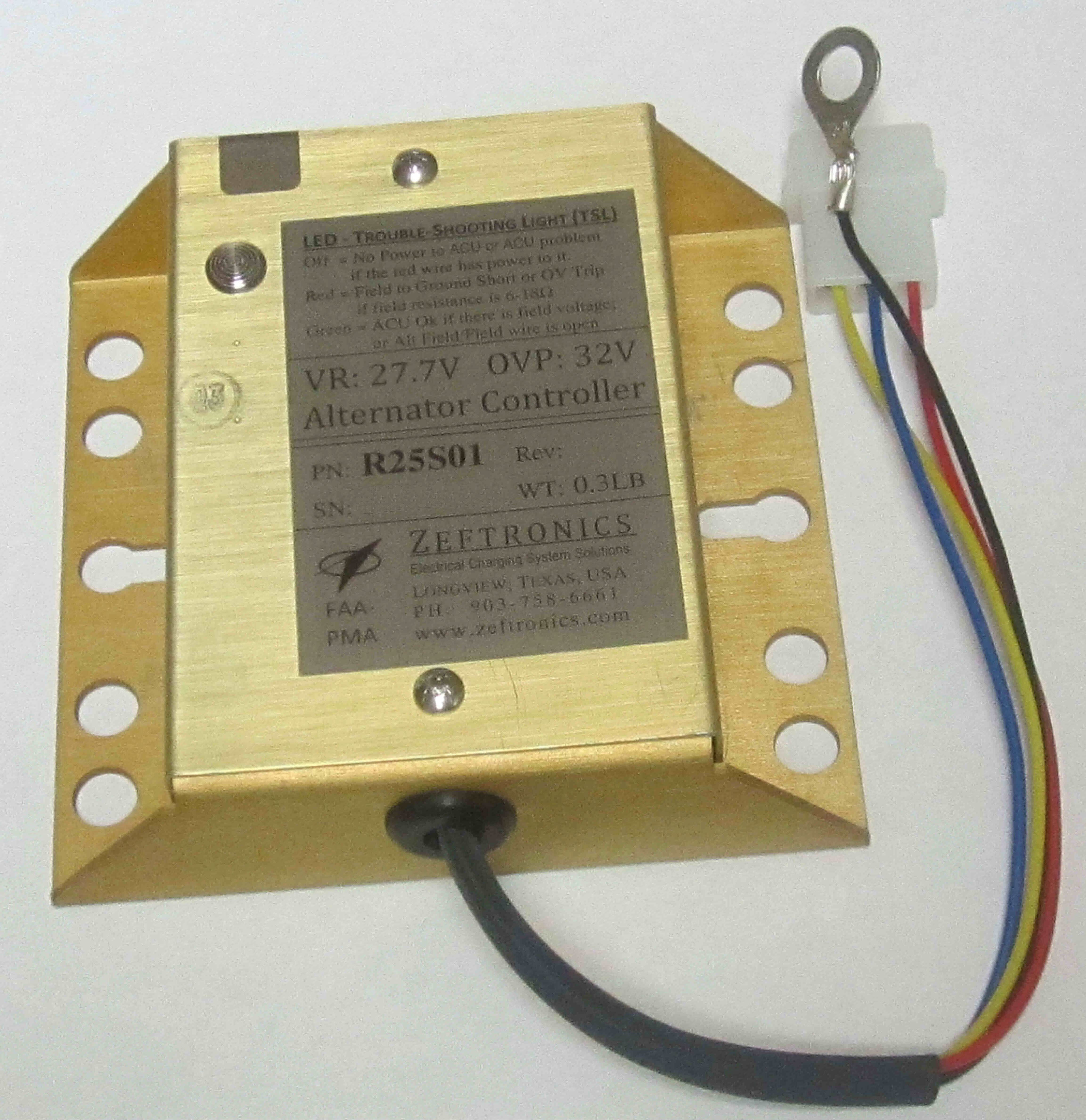
The built in ov sensor provides ov protection by turning off the ov relay inside the controller if the bus voltage exceeds 16v. Features part number r15100 rev a r15v00 r15v00 rev a. Increasing it when the system load increases and decreasing it when the load drops. Green with a sustained bus voltage of 20v to 256v means current is flowing from the acu but the alternator field or field wire to it is open. Wiring diagram bat alt field bus alt out f1 alt f2 40a 100a acu r15300 r1530b 1a 4d 2b 3c 5a bat. C611001 0101 0102 beech pn 33 380010 electrodelta pn vr 600 pftlamar pn.
R15100 separate ovs voltage regulator the r15100 replaces cessna pn.
Gallery of Zeftronics Voltage Regulator Wiring Diagram