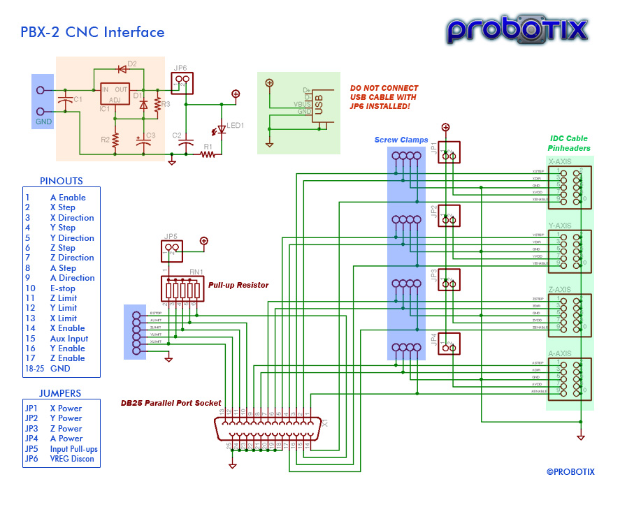
During wiring always unplug the pbx from its power source and plug the pbx phone system back in only after all wiring is completed. I2c header pin diagram speed x y z a gnd x y z 5vdc 1 3 7 2 4 8 10 9 6 5 figure 4.
Spitfire Help Desk Wiring Diagram For Spd 24x48 Pbx
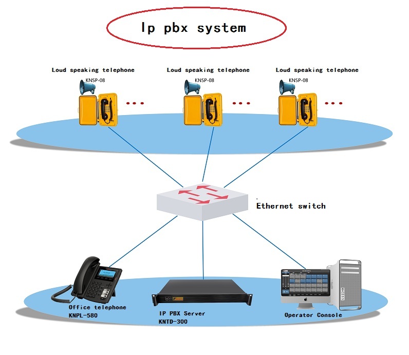
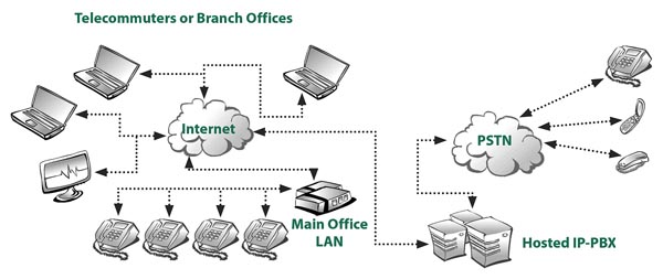
Pbx wiring diagram. T and r represent station connections and should not be confused with tip and ring on external lines. 2 pickup guitar wiring diagrams. 1 2 and 3 as shown below. This diagram shows a private branch exchange pbx system. Pbx stands for private branch exchange which is a private telephone network used within a company or organization. These diagrams show the male grey background and female black background pin numbering for db9 and db25 sub miniature connectors.
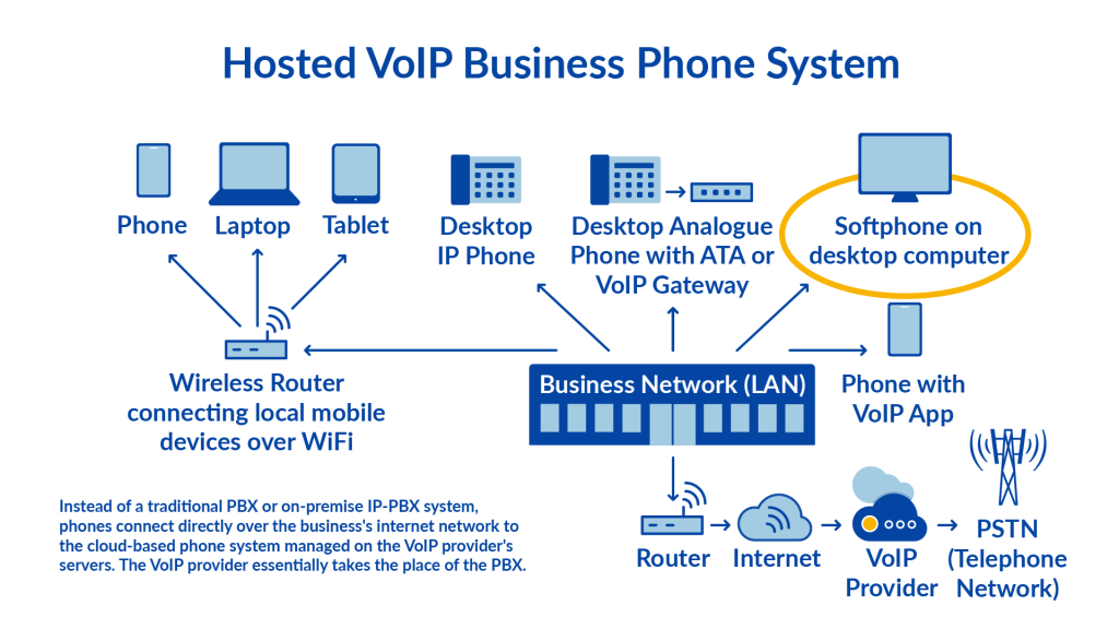
Generally pin 1 is marked on the front of the connector right next to the pin though you may need a magnifying glass to read it. You can edit this network diagram using creately diagramming tool and include in your reportpresentationwebsite. 2 humbuckers w 3 way switch. 2 humbuckers1 single coil. Pmt sonic expansion control diagrams. Always check the extension and if it malfunctions then disconnect the telephone from the extension line and connect it again or turn off the pbx system using the power switch then turn it on again.
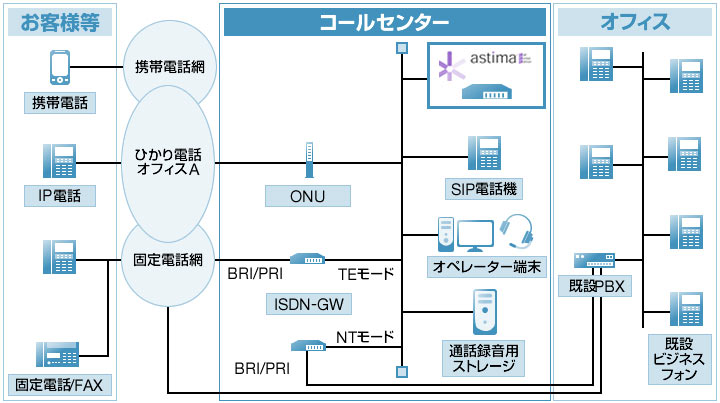
Wiring up isdn cable. Db9 and db25 male and female pin numbering. This diagram shows a pbx with telephone sets voice mail system and trunk connections to pstn. The users of the pbx phone system can communicate internally within their company and externally with the outside world using different communication channels like voice over ip isdn or analoga pbx also allows you to have more phones than physical phone lines ptsn and. Standard cat5 utp unscreened twisted pair cable is recommended for all types of telephone station wiring and should always be used for isdn cabling applications. Ics telephone extns wiring chart.
This is shown in the diagram below. Custom drawn guitar wiring diagrams. 1 humbucker 2 single coils. A network diagram showing pbx. Pbx header pin diagram preliminary manual not yet complete pendant header data clock nc 5vdc gnd gnd 1 3 2 4 6 5 figure 3. Cat5 cable is color coded in pairs and each pair consists of two wires twisted together within the cable.
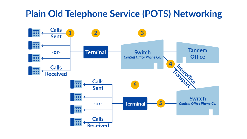
2 humbuckers w 5 way switch. 1 humbucker1 single coil. The voice mail depends on the pbx to switch all calls needing access to it along with the. Pendant header pin diagram 11 12 14 13 16 15 a data e stop a gnd clk e stop b jp1 pot e stop loop jog inputs. The pbx switches calls between telephone sets and also provides them switched access to the pstn. The following wiring charts describe the three ics connectors.
Panasonic pbx door phone door opener and video intercom complete wiring diagram. Norstar ics wiring charts. 3 pickup guitar wiring diagrams.
Gallery of Pbx Wiring Diagram