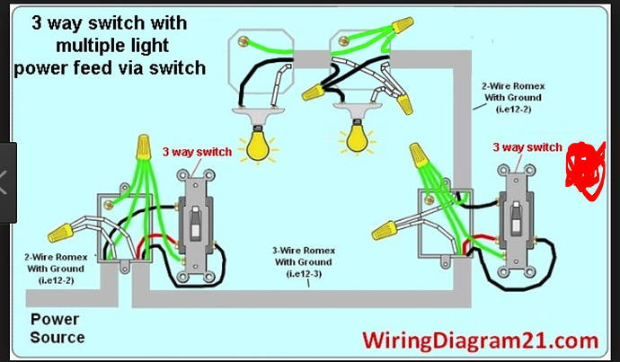
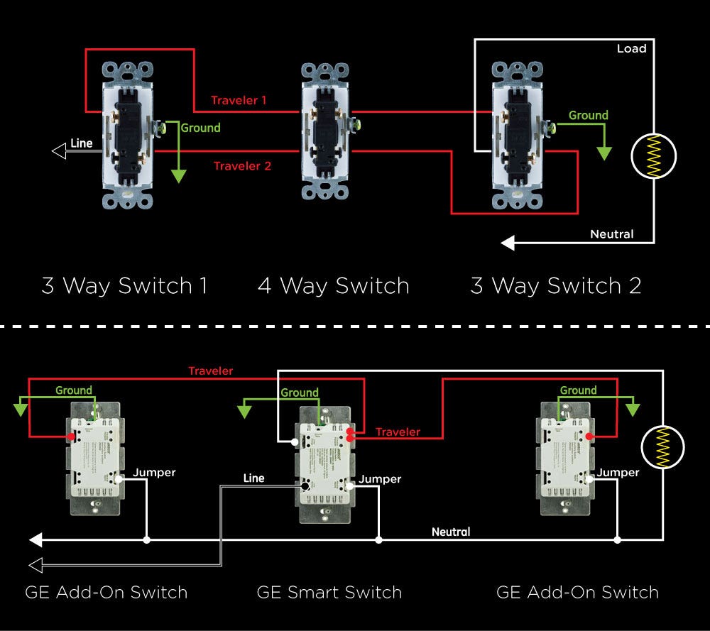
Otherwise the smart switch will be unable to power its wireless communication. Take a closer look at a 3 way switch wiring diagram.

Help Connecting Up Smart Wifi Light Switch Overclockers
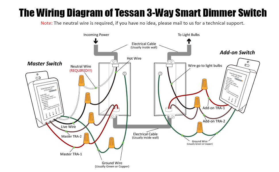
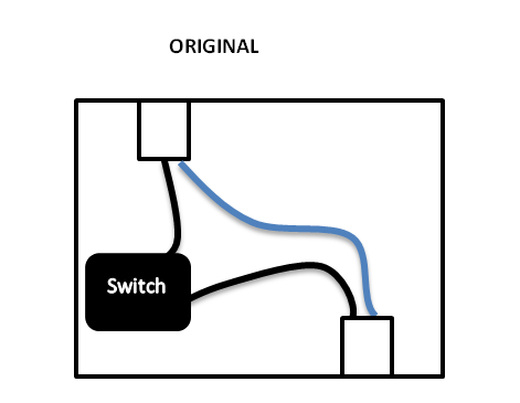
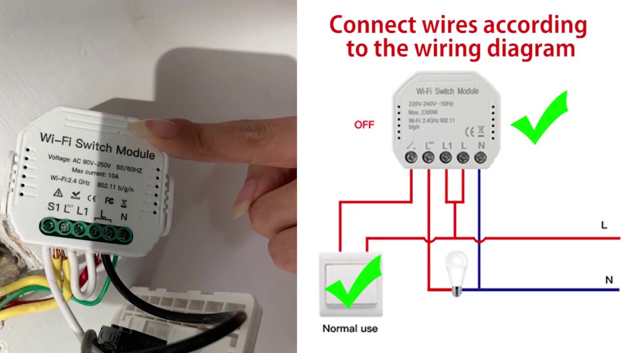
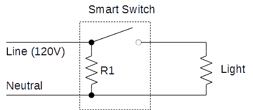
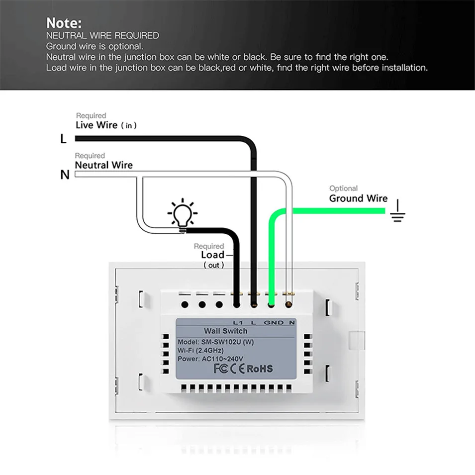
Wifi switch wiring diagram. White neutral wire. Below is a diagram of a smart switch installed in the first configuration with neutral. Notice that regardless of whether the switch is on or off there is a clear path from line to neutral that includes r1. Your homes wiring may differ. You will need to refer to this during the wireless communication setup. Pick the diagram that is most like the scenario you are in and see if you can wire your switch.
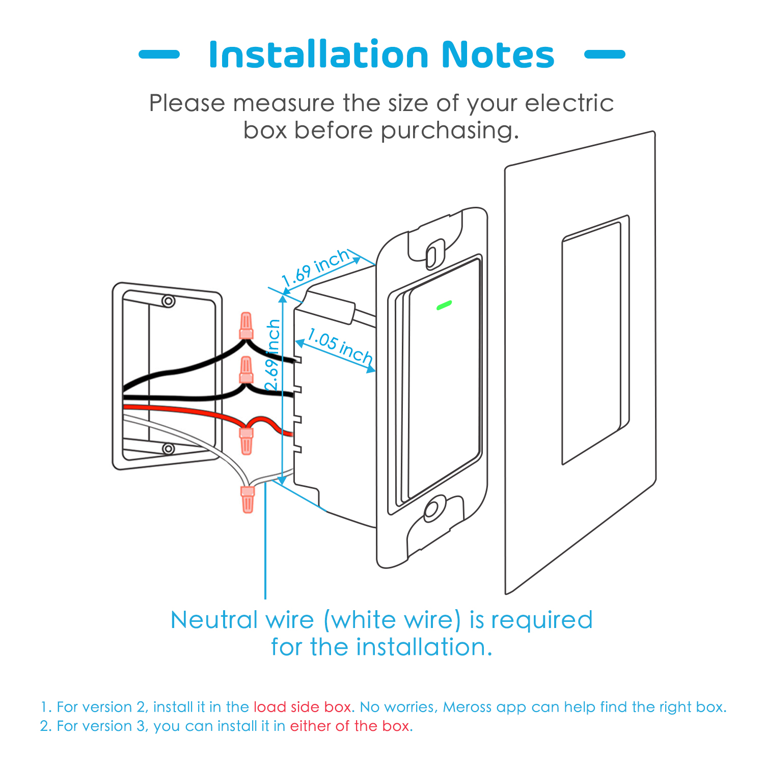
Wiring diagram of a wemo wifi switch with red for load black for line white for neutral and a yellow connected to a green ground wire. The wireless communication setup. The ground wire from the smart switch needs to be connected to that. Yellow ground wire. Each network diagram includes a description of the pros and cons of that particular layout as well as tips for building it. Please consult a qualified electrician.
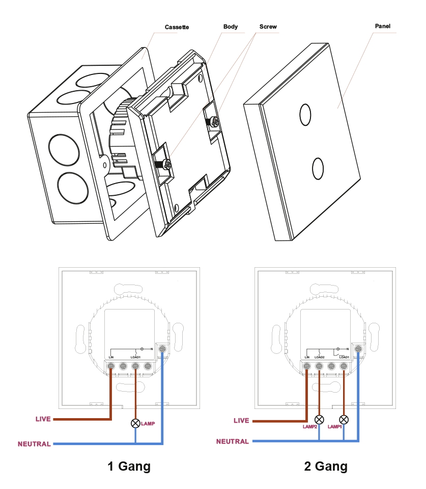
You should see two additional neutral wires connected by a wire nut as well as the line load and ground wires. Smart switch with neutral. This might seem intimidating but it does not have to be. Mark as the primary p switch position. 3 way switch wiring diagram. Black switch line load wire.
The wire you removed from the common terminal that is not energized is the load wire. You need neutral wires to install a wemo dimmer. This gallery contains network diagrams for wireless wired and hybrid home networks. Many home network layouts work fine but most are variations on a basic set of common designs. With these diagrams below it will take the guess work out of wiring. In your switch box you should have one or more grounding conductors spliced together with a wire connector or wire crimp.
Gallery of Wifi Switch Wiring Diagram