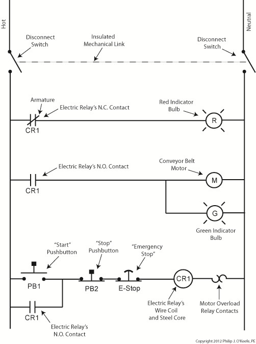
Pump down method step by step 1 ensure the air condition or refrigerant already offuse a multimeter to confirm it have no power supply. Symbols that stand for the components in the circuit and also lines that stand for the connections between them.
Sap Cmrv 1926 3146 Eh Install Manualzz
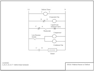
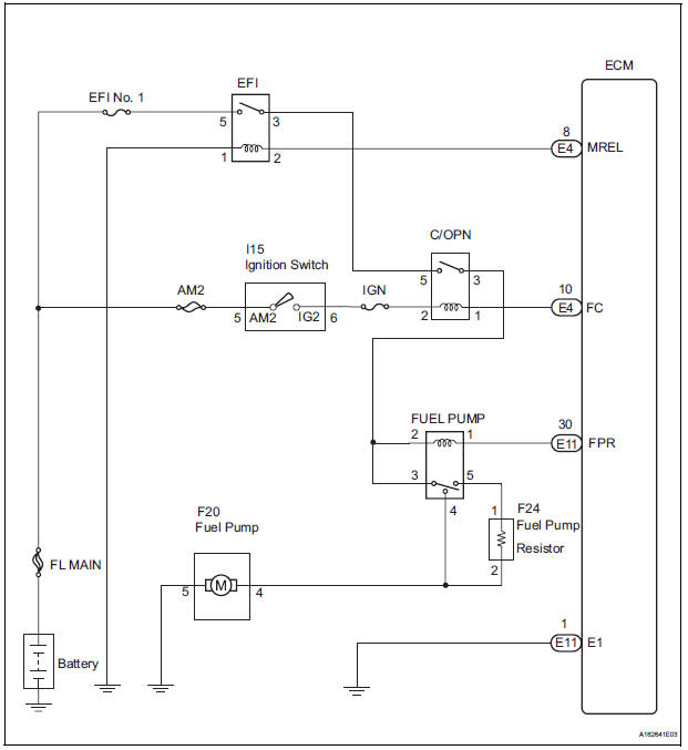
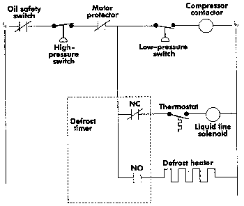
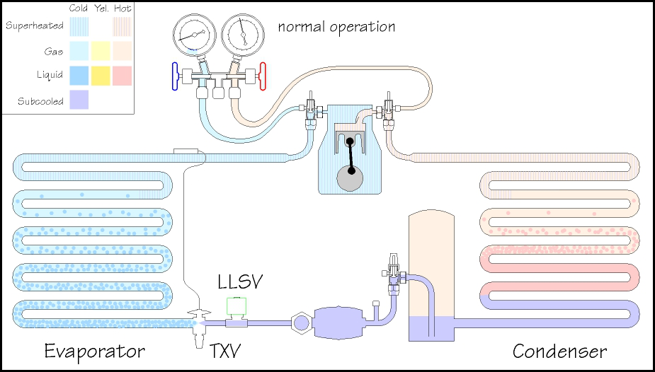
Pump down system wiring diagram. Wiring diagrams are made up of two things. Press t stat on and see that it allows a circuit to the llsv. It shows the components of the circuit as streamlined forms and the power as well as signal connections between the devices. 2 install the manifold gaugeuse a blue hose low pressure meter and connected to the valve for low suction big tubing. The t stat is the operating control but does not directly control the compressor. When trying to locate a component in a wiring diagram and you dont know the specific system where it is located use this handy component locator to find the system wiring diagram in which the component is located.
A wiring diagram is a streamlined traditional pictorial depiction of an electric circuit. Press the off cycle button and note that the evap fans are running constantly. The compressor will continue to pump refrigerant into the condenser andor receiver drawing it from the low side of the system. A system pump down utilizes a solenoid valve in the liquid line when the system set point temperature has been satisfied the solenoid valve will close. The schematic below depicts a simple pump down system. Wiring diagram component locations.
Assortment of fill rite pump wiring diagram. Then go to that system and locate the component within the wiring diagram. A wiring diagram is a kind of schematic which uses abstract photographic signs to show all the interconnections of elements in a system.
Gallery of Pump Down System Wiring Diagram