4 hsync or csync 5 vsync. Reparando cable vga duration.
Ezbnc By Sewell Bnc To Vga Video Converter Sw22418 33 95
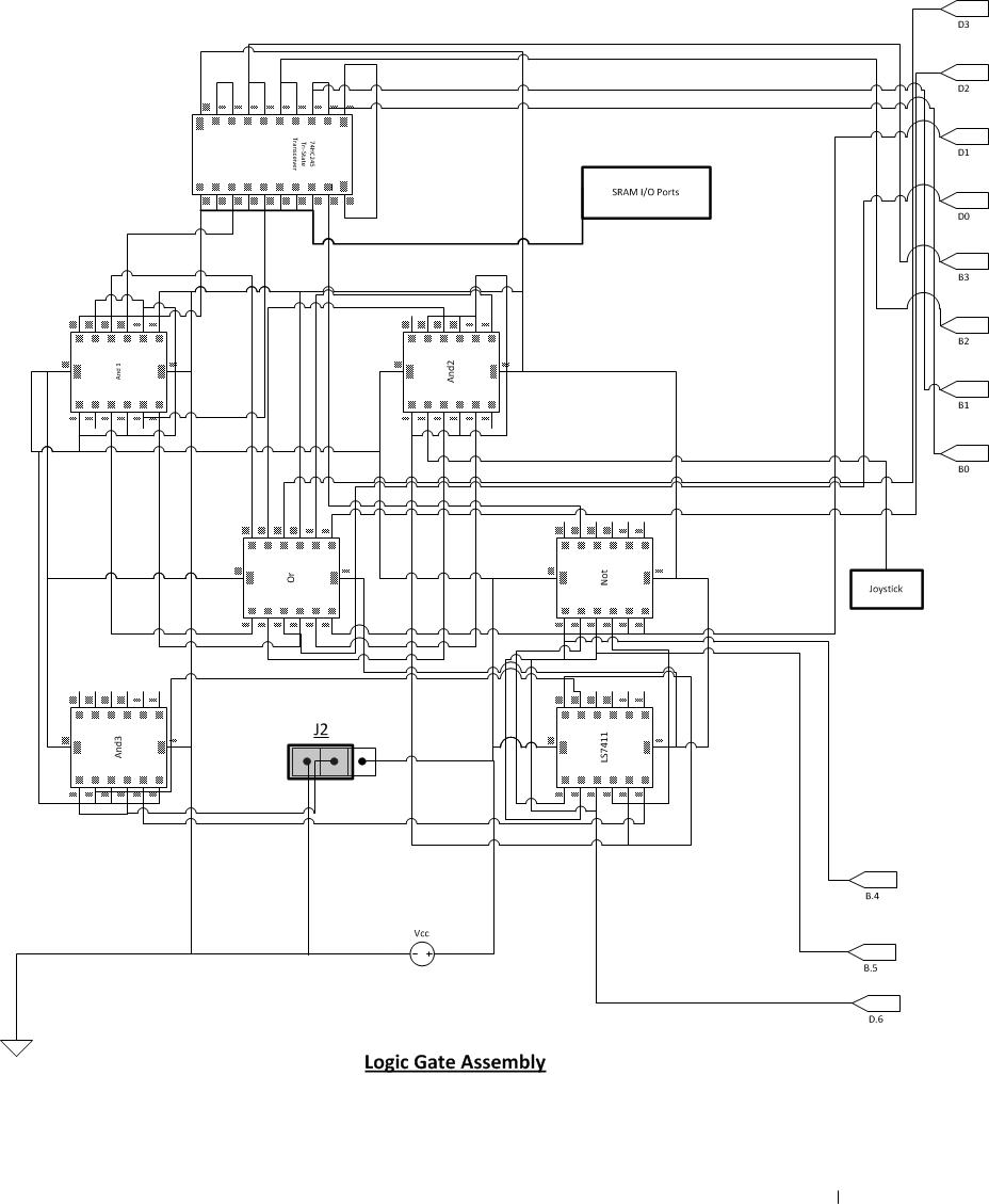
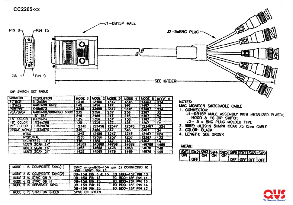
Vga to bnc wiring diagram. Vga bnc adapter circuit diagram an exor gate from ic1 74hc86 combines the separate v sync and h sync signals into a composite sync signal. Jp1 can then by used to select the correct operating mode. 4 hsync or csync. Vga to av converter diagram rca cable to hdmi for old tv to smart tv duration. Buy at svideo com. Once you have ran the cable and have the camera mounted you must have the right fitting in the correct side.
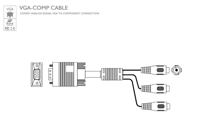
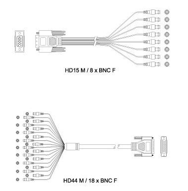
Before learning how to splice bnc to usb wiring diagram there is something to find out about this particular cable. Vga to 5 bnc cable with a male vga connector and 5 male bnc connectors. Since the sync in dos modes is often inverted compared to the modes commonly used by windows the output of ic1a is inverted by ic1b. It can also link device to a power source for charging function. The initial one is low rate with transfer rate about 15 mbit per second. There are four kinds of data rates in usb cable.
Monitor id bit 0 optional bnc sync ground. Since the sync in dos modes is often inverted compared to the modes commonly used by windows the output of ic1a is inverted by ic1b. You will need to make sure the color matches on. A wiring diagram is included with each of our baluns. The rgb signals from the vga connector are fed to three bnc connectors via ac coupling capacitors. The majority of them use usb cable.
Hdmi to vga wiring diagram hdmi to vga cable wiring diagram hdmi to vga connector diagram hdmi to vga converter wiring diagram every electrical arrangement is made up of various distinct pieces. These have been added to stop any direct current from entering the vga card. Bachiller channel 54479 views. The cable can be utilized to transfer data from one device to another. Jp1 can then by used to select the correct operating mode. Vga bnc adapter circuit diagram an exor gate from ic1 74hc86 combines the separate v sync and h sync signals into a composite sync signal.
Each component should be set and connected with other parts in specific way. Bnc to usb wiring diagram bnc to usb wiring diagram there are a number of types of electronic gadgets on the market. A pull up resistor on the green output provides a dc offset while a transistor a bs170 mosfet. Otherwise the arrangement will not function as it should be.
Gallery of Vga To Bnc Wiring Diagram