In many wiring diagrams the brake voltage is tapped directly from the motors terminal. Dr motor frame size wire length thomas betts ring terminal thomas betts crimp tool dr71 100 8 rb14 8 wt2000.
460v 12 Lead Motor Wiring Diagram Diagram Base Website Wiring
Sew motor wiring diagram. Back to top. 2010 dr motor common connection diagrams 3 table of contents. Wiring diagrams brake rectifiers and coil data. Observing the wiring diagram. Always use wiring diagram supplied on motor nameplate. Assortment of sew eurodrive motors wiring diagram.
It shows the parts of the circuit as simplified forms and the power as well as signal links in between the devices. 221 machine electrical system 5 inqerht singerlight and three pin terminal d lack ro outlet ell 006 yeo w termma e11005 universal controller and three pin terminal switch yellow fie a threepin. Dr motor common connection diagrams edition 062010 9pd0058 us. Connection diagram dt13 examples motor voltages. When the motor is connected the distances to non. Motor wiring diagram of brs sewing l amp 10 canttder unit to motor puey end motor wiring of by family sewing machine c.
Available from sew the ur relay mounts directly to the motors. The customer has to supply additional wiring and a motor starter that contains an extra contact. For an extra contact or extra wiring. Motor connection diagrams uscs 0100. Drive engineering practical implementation. Ac motors dr71 225 315 operating instructions.
10232000 121725 pm. Brake voltage matches low. A wiring diagram is a simplified standard pictorial representation of an electrical circuit. Use the cable end equipment intended for this purpose. Establish a secure protective earth connection. The bmk brake control system optional for frame sizes 71 to 225 the bmk rectifier functions like the rectifier type bge.
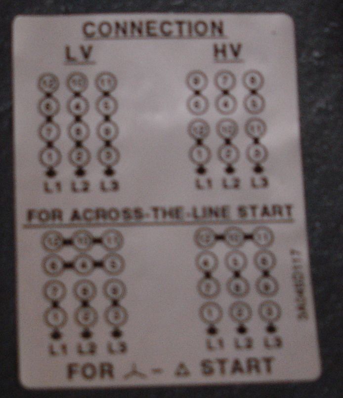
200 346y volts 60 hz 330 575y volts 60 hz 220 380y volts 50 hz 1 motor wired for low voltage. Gear units r7 f7 k7 s7 series spiroplan w operating instructions cm synchronous servomotors. Motor connection diagrams installation instructions 2000 01 created date. The connection should be a continuous secure electrical connection no protruding wire ends.
Gallery of Sew Motor Wiring Diagram