Owned by major tech veti is a brand that focuses on stylish and modular electronic fittings including switch boards light switches lights and plugs. Simply strip the wire to the length specified and push the wire into the hole.

T8 Led Wiring Diagram Together With Fluorescent Light Circuit
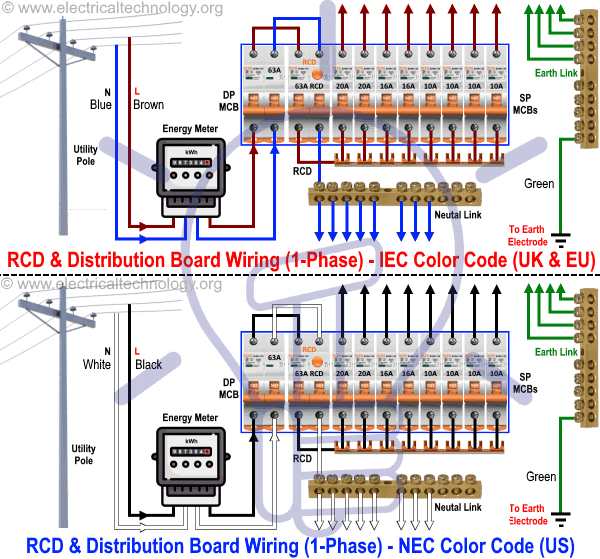
Veti light switch wiring diagram. Two way switching 2 wires. Switches are shown as dotted rectangles. 360 detection field automatically turns on lights when motion and body heat is detected 3 2000 lux adjustable installation height 15 35m identify day and night automatically time delay and ambient light adjustment. Questions about wiring switches. This site is merely. How to wire a gfci and outlet to a light switch.
This diagram illustrates wiring for one switch to control 2 or more lights. Just click the wiring diagrams. The source is at sw1 and 2 wire cable runs from there to the fixtures. The switch terminals are clearly numbered with a corresponding wiring diagram on the side of the switch to make installation and connection as simple as possible. You have an incoming hot wire black going to one screw it does not matter if you use the brass or silver screw on the side of the 2 way switch and a black wire from the other screw on the 2 way switch going to the load light ceiling fan etc. These diagrams show various methods of one two and multiple way switching.
The hot and neutral terminals on each fixture are spliced with a pigtail to the circuit wires which then continue on to the next light. Fully explained wiring instructions complete with a picture series of an installation and wiring diagrams can be found here in the gfi and light switch area here in this website. Notice the black wire is the only wire that we are controlling through the 2 way switch. This light switch wiring diagram page will help you to master one of the most basic do it yourself projects around your house. The most basic circuit with only two wires at the switch. Wiring a single pole light switch.
Hey doing it yourself is great but if you are unsure of the advice given or the methods in which to job is done dont do it. Connect the source wire to the bottom terminal of the switch and the other black wire to the top terminal. L and n indicate the supply. This gauge is when you want to use the quick connect method when wiring a light switch. Earth wires are not shown. In this picture you can see the strip gauge on the back of the switch.
Multiple light wiring diagram. The switch terminals use a clamping mechanism as opposed to a screw connection in order to prevent stranded cable from breaking and coming loose.


