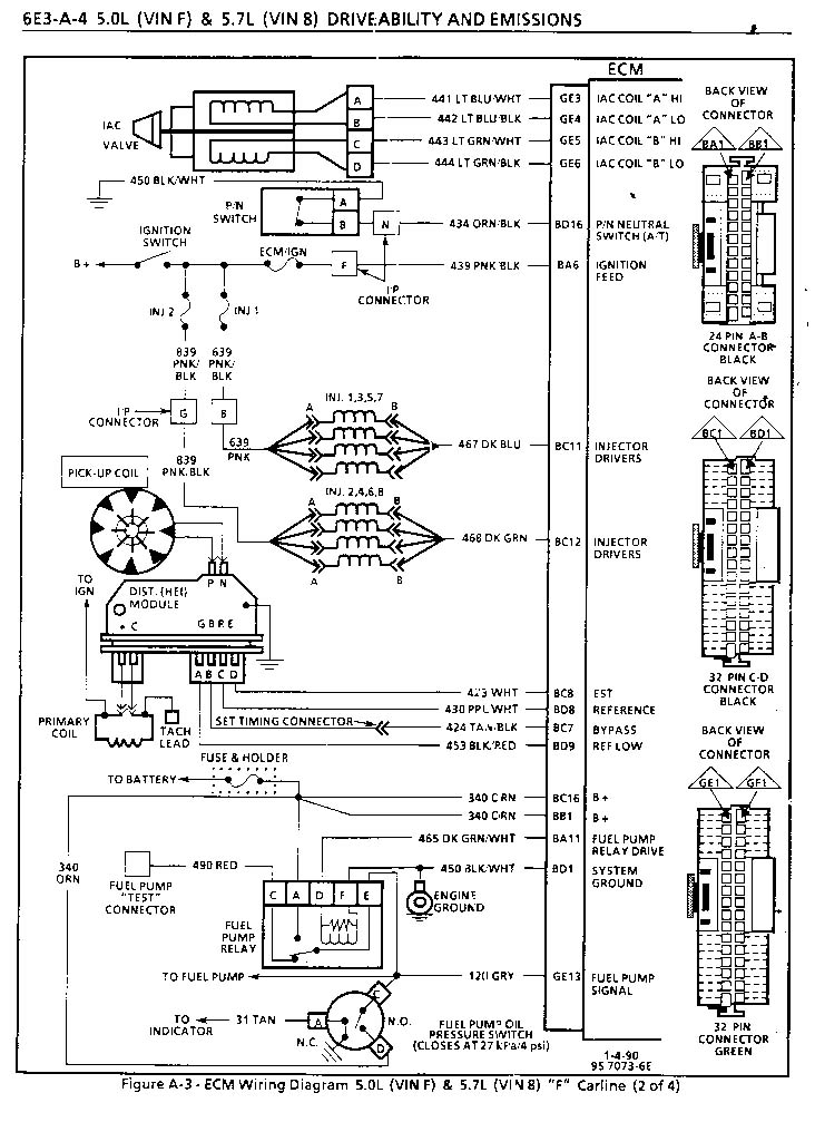
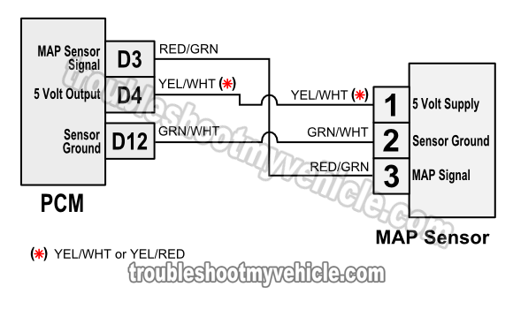
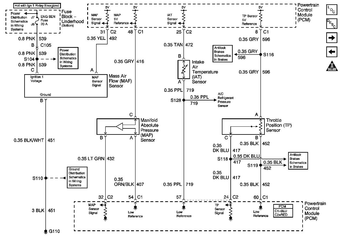
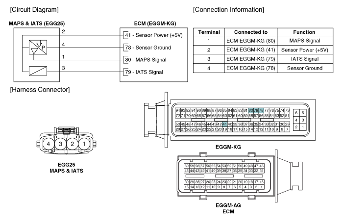
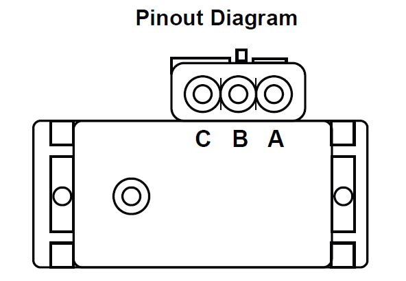
Map sensor wiring diagram for maf. Backprobe with a high impedance voltmeter at map sensor terminals a and c.

36 Isuzu Trucks Service Manuals Free Download Truck Manual
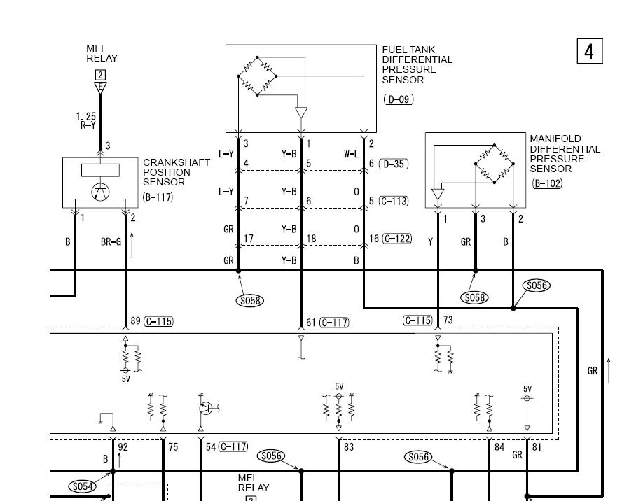
Map sensor wiring diagram engine. For resources on getting wiring diagrams for your vehicle see our article. Youll also find the power and ground circuit wiring diagram of the fuel injection computer. Karen bu projects to try. With the key on and engine off the voltmeter reading should be approximately 50 volts. Video sharing camera phone video phone free upload. This sensor detect the intake manifold pressure change value and converts it into a signal.
A map or a maf will have 3 wires. Map sensor testing see figures 3 4 and 5. Map sensor wiring diagram. Wire installation car fix engine repair buggy car hacks diy electronics electric cars planer cars. Ford f150 engine diagram 1989 04 lariat 4x2 f150 stock 98 nascar edition 4x2 f150. If the voltage is not as specified either the wiring to the map sensor or the ecm may be faulty.
This is a image galleries about map sensor wiring diagram for mafyou can also find other images like wiring diagram parts diagram replacement parts electrical diagram repair manuals engine diagram engine scheme wiring harness fuse box vacuum diagram timing belt timing chain brakes diagram transmission diagram and engine problems. But if you dont have a wiring diagram you can still find your signal wire by measuring it. The map sensor or manifold air pressure sensor is a main input to the ecm or engine control module. Throttle position sensor tps manifold absolute pressure map sensor engine coolant temperature ect sensor intake air temperature iat sensor and the vehicle speed sensor vss. Wiring diagram includes the following circuits. This can tell you the exact wire and its color code and save you some time.
Gallery of Map Sensor Wiring Diagram Engine


.gif)