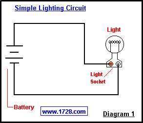
You can see that a spst toggle switch only has 2 terminals. The switch will either be closed or completely disconnected.
Toggle Switch Wiring
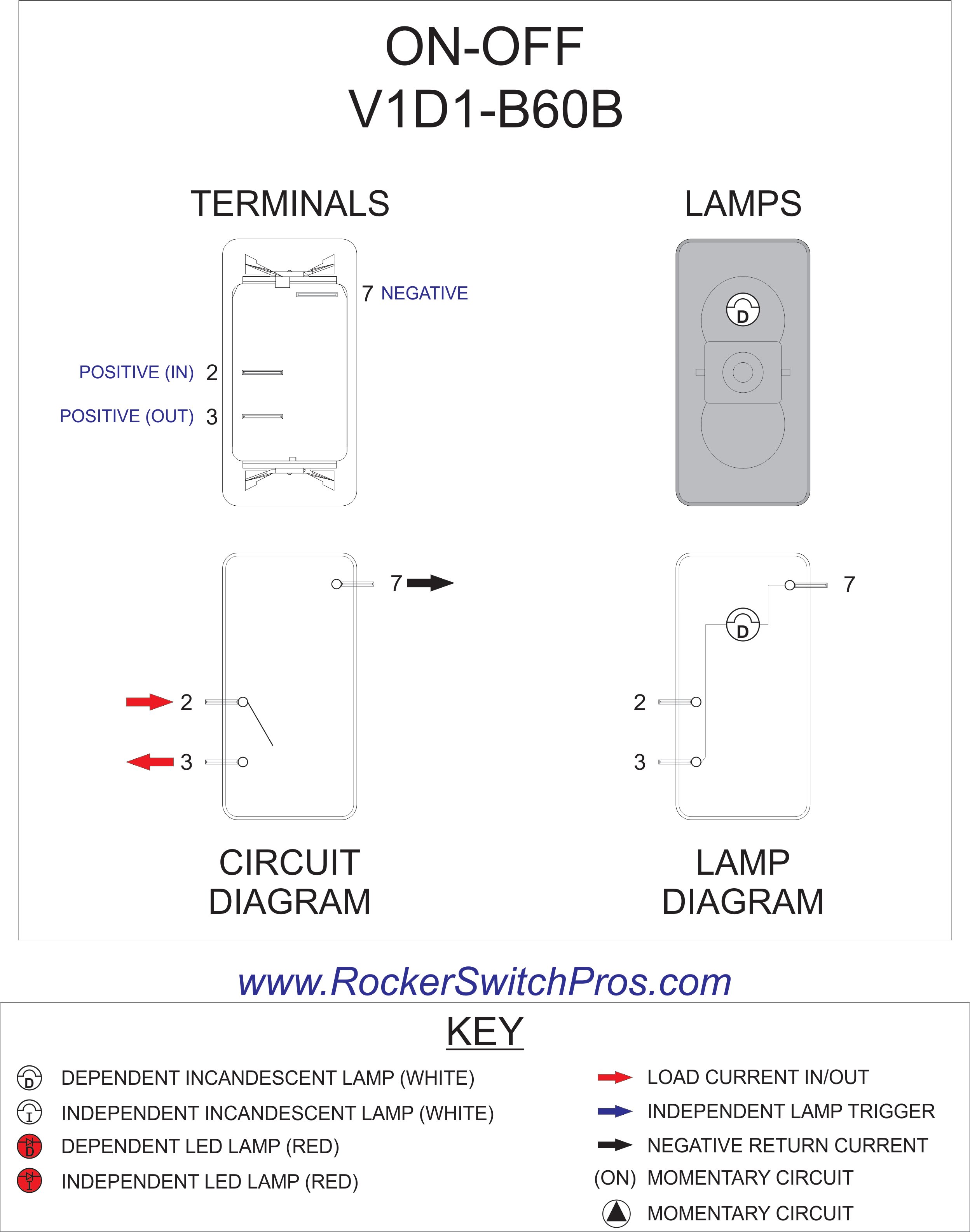
Spst switch wiring diagram. Theyre also a very common form of momentary switches. You might want to review the article on toggle switch wiring before proceeding. Connect the lamp 1 to the upper terminal of spst switch. Dp switches control two independent circuits and act like two identical switches that are mechanically linked. Pin 1 is where the rocker switch receives the input power. An illuminated rocker switch is like a spst toggle switch with an extra terminal which allows the light to work.
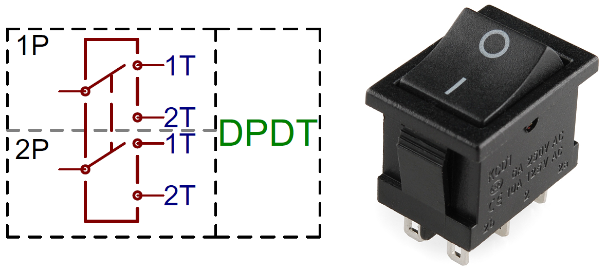
The diagram below represents the schematic diagram for a spst rocker switch. Pin 3 is where the switch is either connected to ground or left open. Connect the lamp 2 to the common middle terminal of spdt switch shown by blue wire in the circuit diagram. Pole refers to the number of circuits controlled by the switch. Sp switches control only one electrical circuit. Spst toggle switch wiring.
What do spst spdt dpst and dpdt mean. Spsts are perfect for on off switching. Spst switches should only require two terminals. Sp and dp refer to single pole and double pole st and dt refer to single throw and double throw. Also relays can be used to switch higher draw accessories to reduce switch load and voltage drop. A single pole single throw spst switch is as simple as it gets.
Spst toggle switches function as simple on off switches. Pin 2 is where the accessory that the switch is going to turn on is connected. The other terminal is for the output. We will now go over the wiring diagram of a spst toggle switch. Its got one output and one input. Below is the wiring schematic diagram for connecting a spst toggle switch.
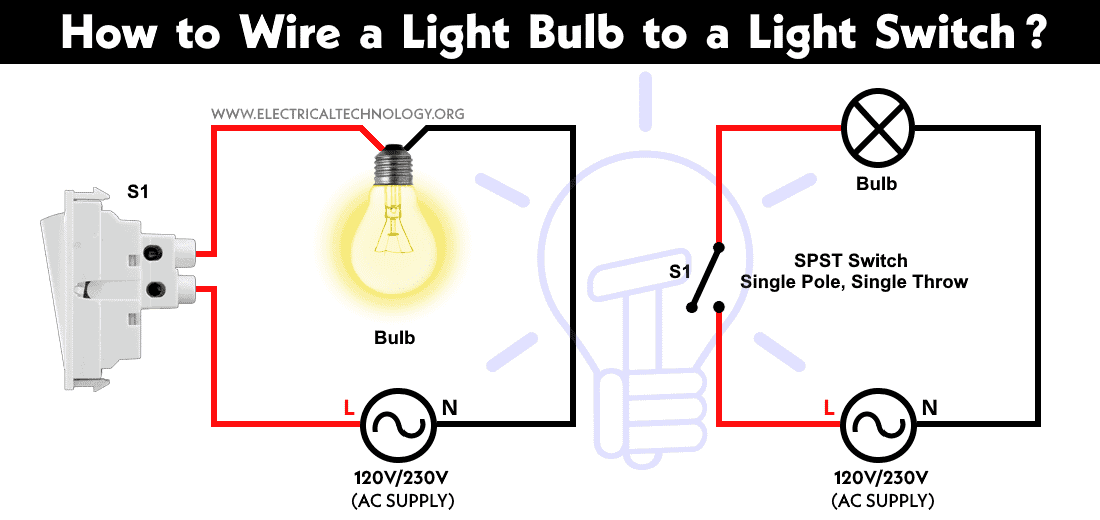
Connect the live line or phase wire to the lower terminals of spst 1 way and spdt 2 way switches. Do the proper earthing and grounding according to your local area codes. 1 terminal is for the input.
Gallery of Spst Switch Wiring Diagram