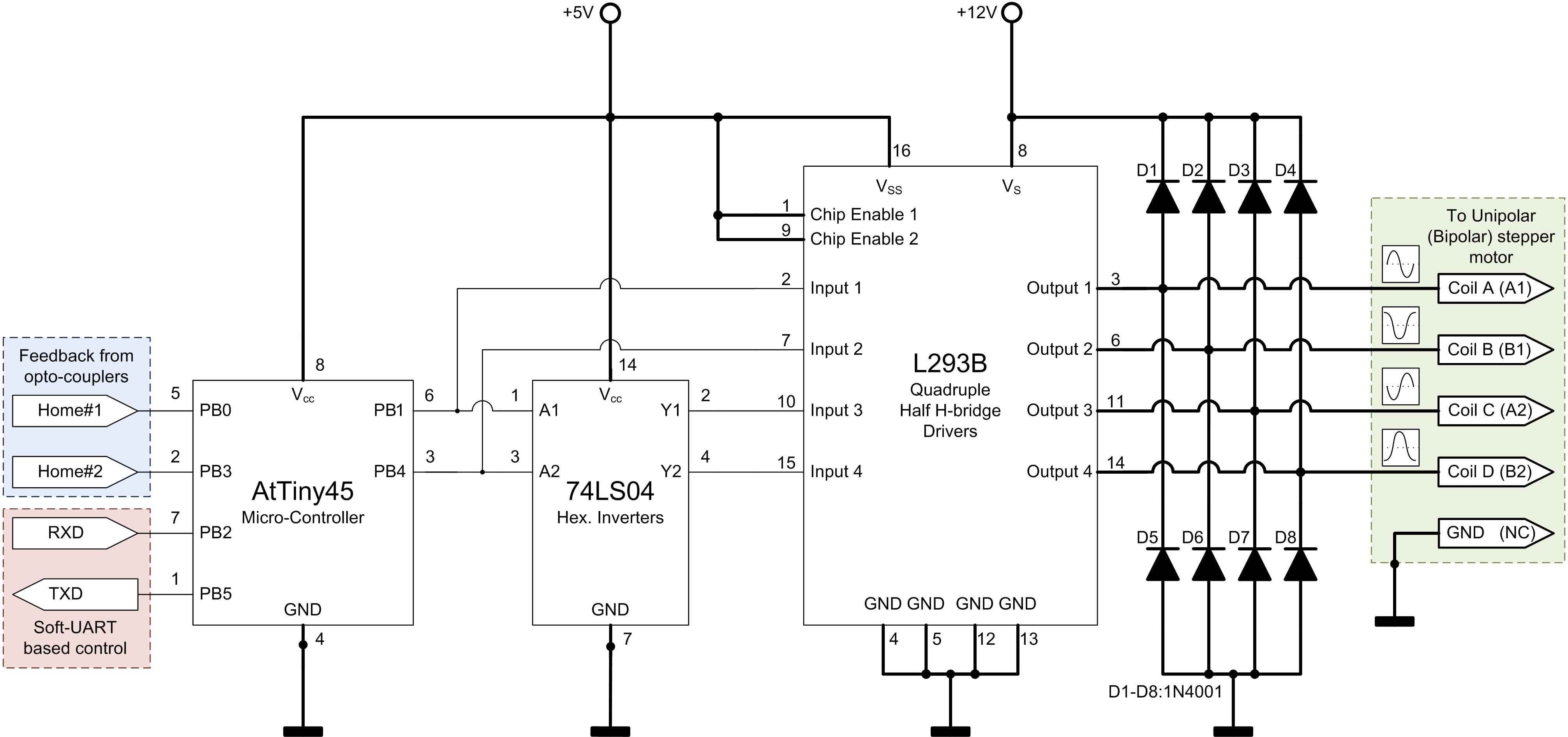
Texas instrument tl494 operational test circuit diagram waveforms and datasheet if you need a power supply control device which has all the functions of pulse width modulation control circuit in a single chip. It shows the components of the circuit as simplified shapes and the faculty and signal contacts amongst the devices.
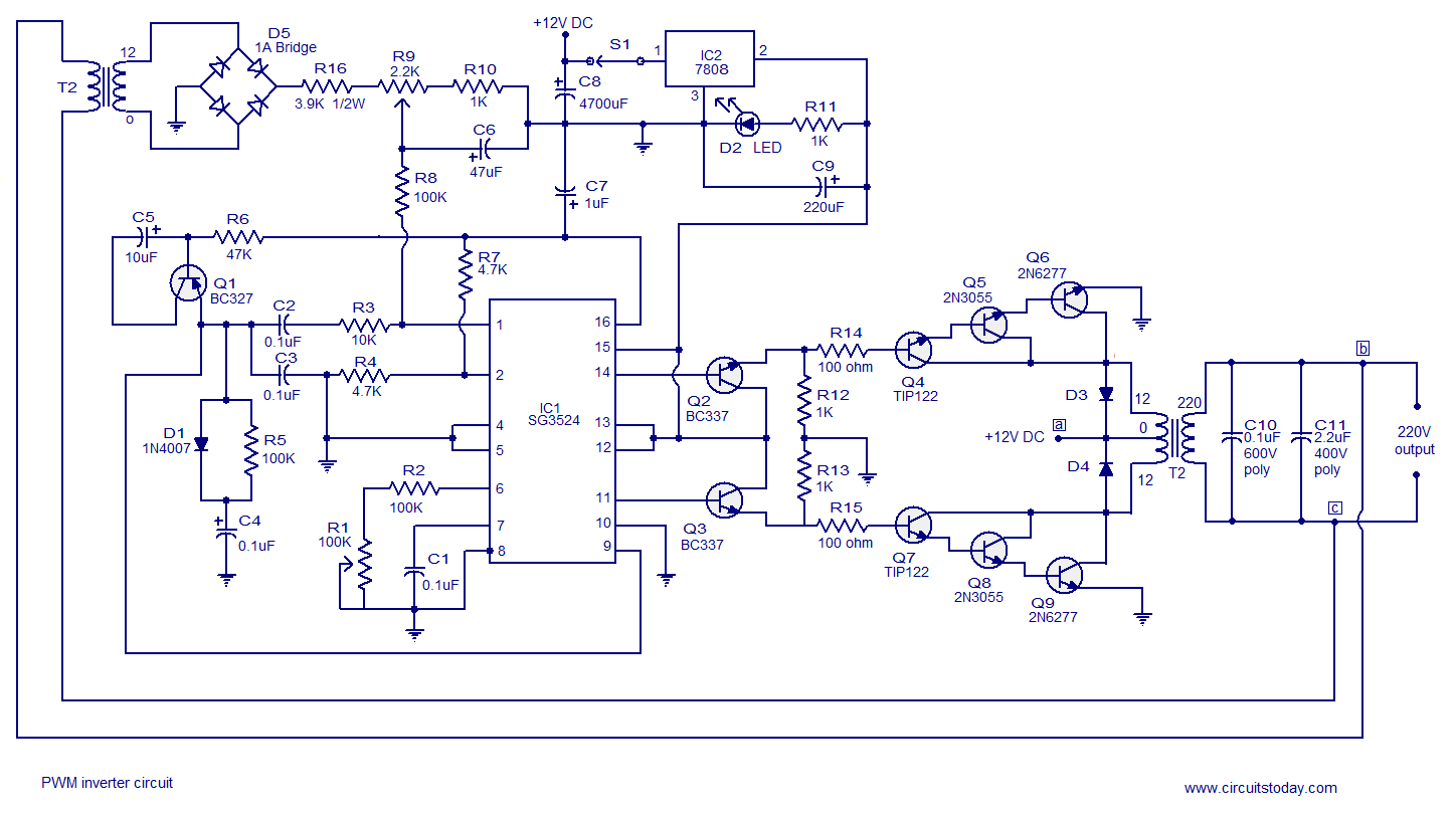
B154d83 Pwm Schematic Wiring Resources
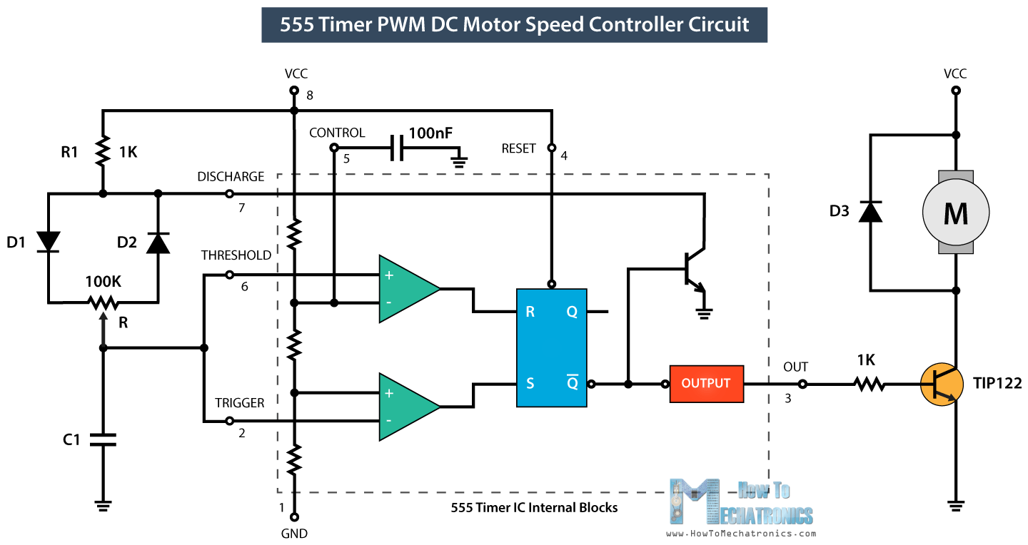
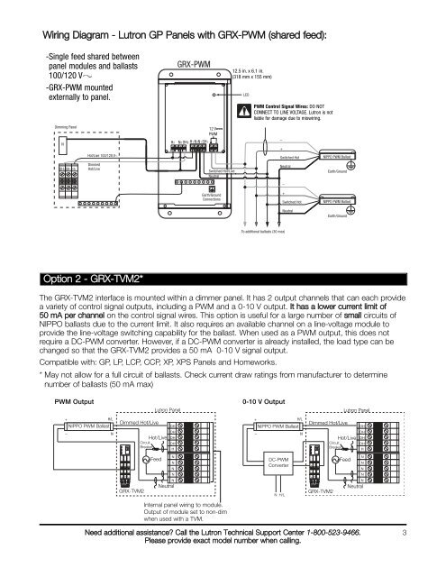
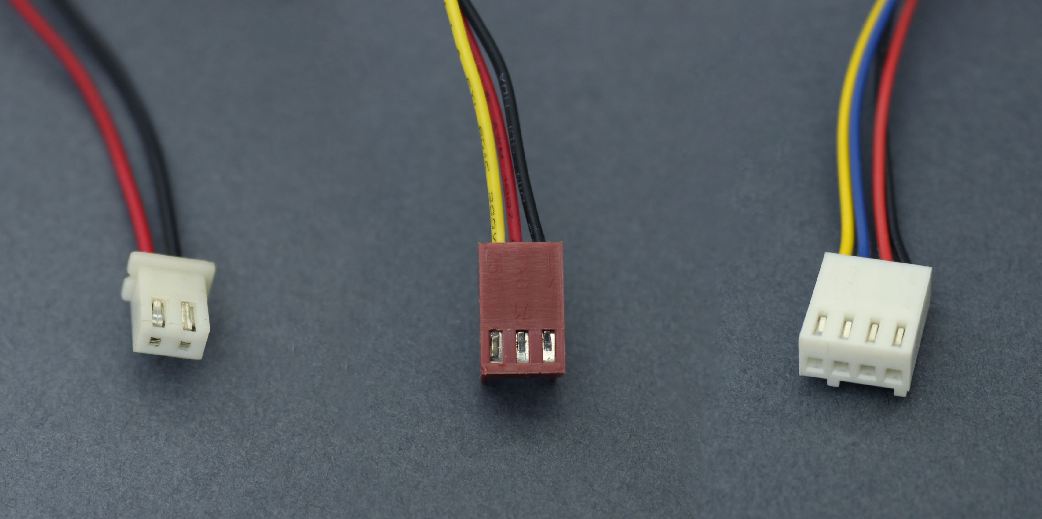
Pwm wiring diagram. 3 pin fan and 4 pin motherboard connector compatibility. The pwm signal from the motherboard sources 5v during the on state of the pulse otherwise its pulled to ground. The image of pwm circuit wired in the breadboard is given below. The tacho signal from the fan sinks to ground for every revolution the input on the motherboard is pulled high. The amplitude of the sine wave should be adjusted in such a way that it matches with the amplitude of the ramp signal generated. Weve published different types of pwm circuits say from the basic pwm using ne 555 ic to the much advanced pwm using micro controllers like avr 8051 and arduino boards.
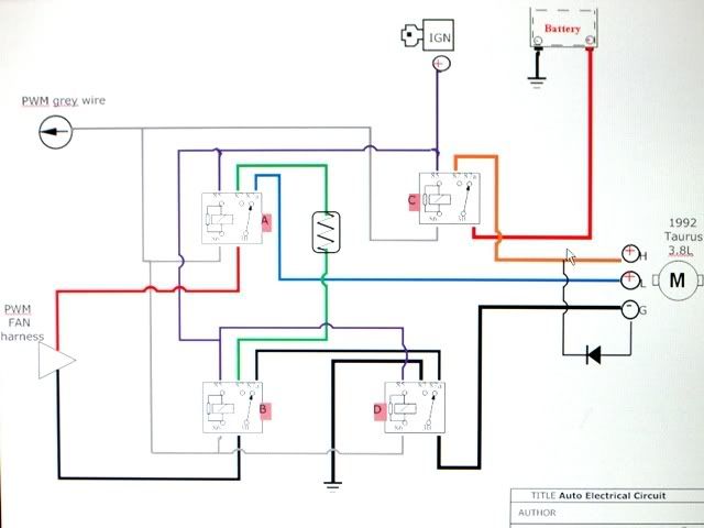
In this project guide were building pwm motor speed control circuit using two digital ics. Pwm is basically pulse width modulation and if youre new to this please go through our basic guides pulse. Circuit diagram of pulse width modulation pwm the 1m ohm resistor is used to adjust the amplitude of the sine wave signal generated by the wbo. Pwm wiring diagram wiring diagram is a simplified satisfactory pictorial representation of an electrical circuit.


