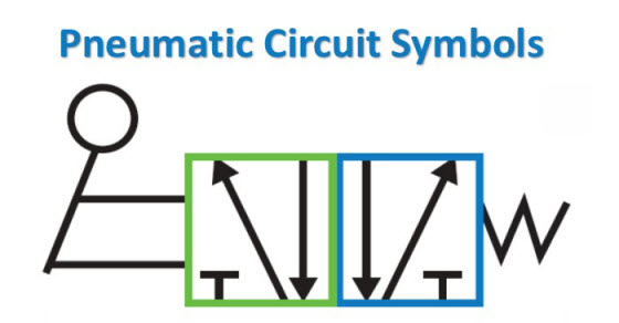
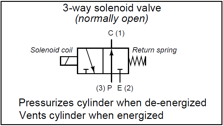
Pneumatic circuit symbols representing these valves provide detailed information about the valve they represent. Provision must be made to prevent power.
Pneumatic Solenoid Valve Diagram Diagram Base Website Valve
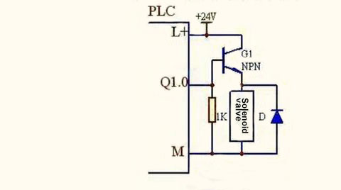
Pneumatic solenoid valve wiring diagram. Use wire number 2 for single solenoid valves and wire numbers 1 and 4 for double solenoid valves as positive. Solenoidvalve work connections and testing pneumaticvalveconnection duration. Our numatics product line has a history of technological breakthroughs. A solenoid electromagnet with its core a valve body containing one or more orifices flow through an orifice is shut off or allowed by the movement of the core when the solenoid is energized or de energized. First to operate solenoid valve we require to give first supply to solenoid coil. Super easy boat wiring and electrical diagrams.
Avoid typical problems when installing a solenoid valve. Wiring an irrigation solenoid valve duration. Asco valves have a solenoid mounted directly on the valve body. An interruption of 10 milliseconds or greater to the power supplied to the solenoid of a solenoid operated valve may cause the valve to shift. Suppression coils are polarity sensitive. It shows the parts of the circuit as simplified forms and the power and also signal connections between the devices.
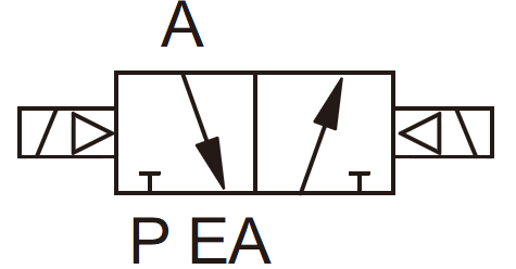
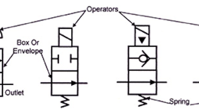
In this video we explain how pneumatic solenoid valve and also explain to operated cylinder with solenoid valve. Symbols show the methods of actuation the number of positions the flow paths and the number of ports. Variety of asco solenoid valve wiring diagram. It shows the parts of the circuit as simplified shapes and also the power as well as signal links in between the tools. Wiring a solenoid valve duration. A solenoid valve is a combination of two basic functional units.
Rajesh electrical 9255 views. Asco is an innovation leader in pneumatics and motion control. Here is a brief breakdown of how to read a symbol. How to use a pneumatic solenoid valve duration. A wiring diagram is a streamlined standard pictorial representation of an electric circuit. Presented by industrial equipment co.
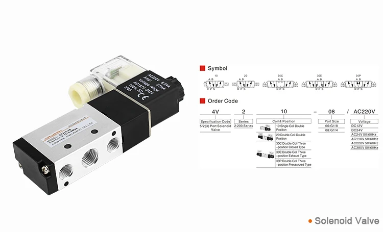
It offers a broad range of 2 3 and 4 way air piloted and solenoid operated directional control valves with fieldbus and io capabilities. Assortment of smc solenoid valve wiring diagram. A wiring diagram is a simplified standard pictorial depiction of an electric circuit. Directional air control valves are the building blocks of pneumatic control.
Gallery of Pneumatic Solenoid Valve Wiring Diagram