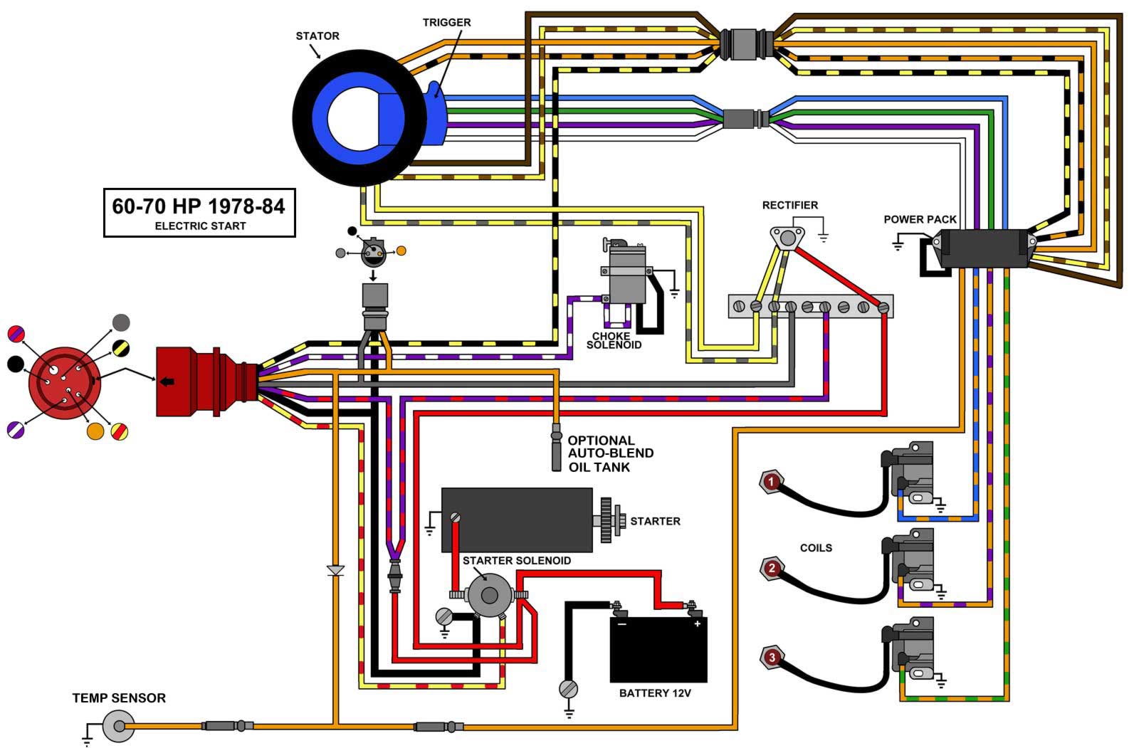
A wiring diagram is a simplified standard pictorial representation of an electrical circuit. Temperature switch to warning horn andor temperature sender to temperature gauge.
Evinrude Etec Ignition Switch Wiring Diagram Wiring Diagram
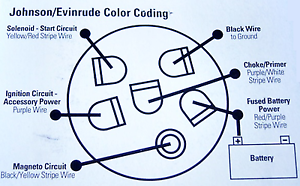
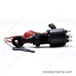
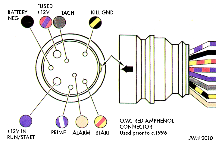
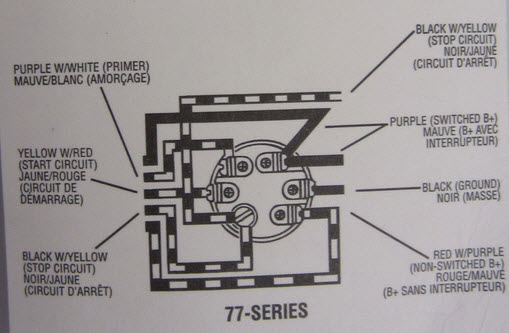
Omc ignition switch wiring diagram. Find ignition switch with key and lanyard 5005801 here. The ignition switch on most outboard motors is operated by a key much like used traditionally in vehicles. Un fused wire from battery. Collection of evinrude ignition switch wiring diagram. V 4 motors 1982 1984. Yellow andor yellow w gray stripe.
A wiring diagram is a streamlined conventional photographic representation of an electric circuit. V 4 motors 1973 76 cd ignition. We have actually accumulated numerous pictures ideally this image is useful for you as well as help you in finding the answer you are trying to find. Offering discount prices on oem johnsonevinrude omc parts for over 50 years. Collection of johnson outboard ignition switch wiring diagram. 5 in stock ships immediately.
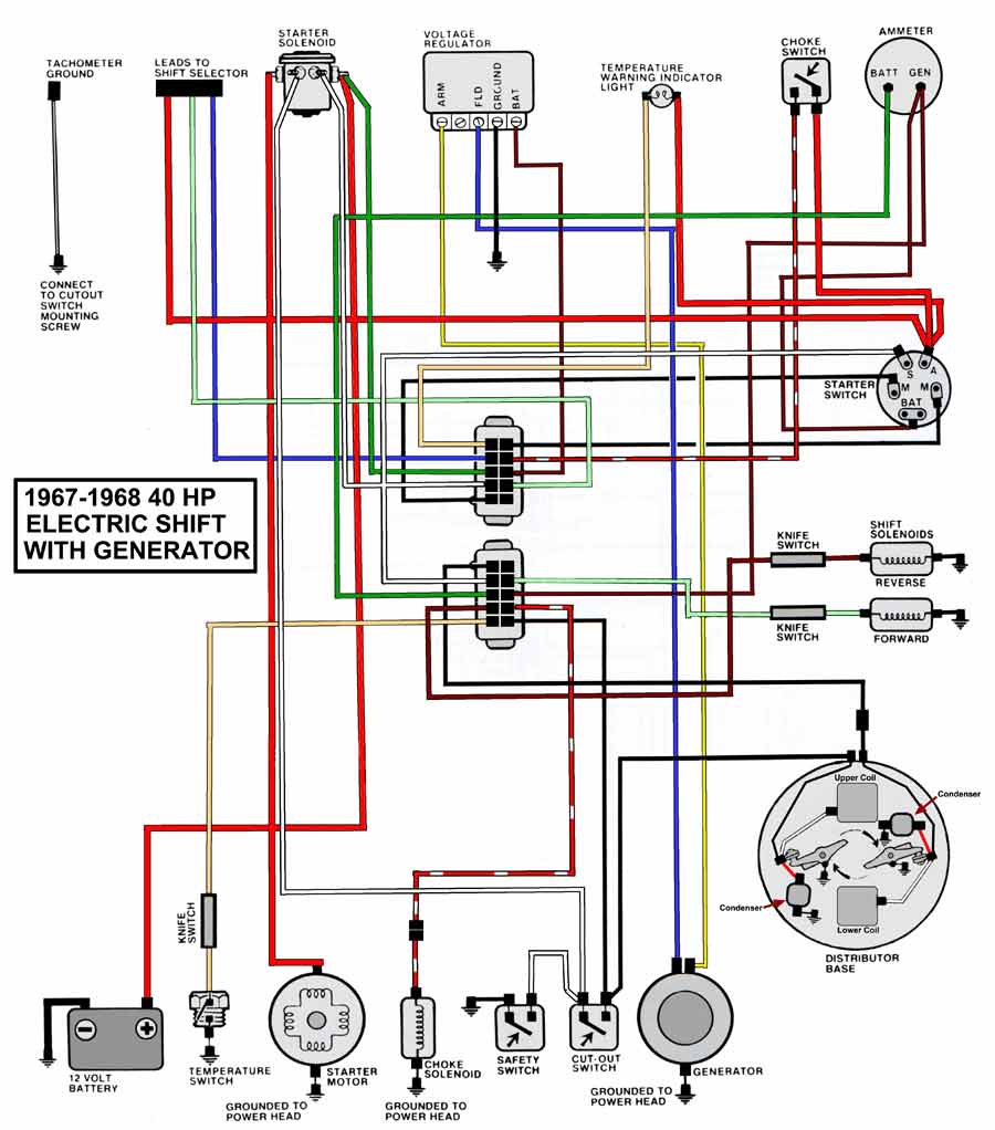
Ignition switch to neutral start switch. It shows the components of the circuit as streamlined forms and the power and also signal links in between the tools. V 4 85 hp motors 1969 70 walternator. Offering discount prices on oem johnsonevinrude omc parts for over 50 years. This description is specific to omc outboard motors but will be typical of most. It shows the parts of the circuit as streamlined shapes and the power and also signal links in between the gadgets.
Tan with or without stripes. The switch configuration and wiring is fairly standardized. 5 arriving soon leaves in 3 5 days. Find ignition switch 0508180 here. Most outboard motors are operated and started using a key ignition switch. Evinrude ignition switch wiring diagram thanks for visiting my site this post will discuss regarding evinrude ignition switch wiring diagram.
Ignition switch to 12 volt positive. Stator to regulator charging circuit yellow with red stripe. However variations can exist such as between remote control and tiller models. Outboard wiring diagrams these diagrams are accurate to the best of our knowledge. Note that the nut on the positive battery terminal that holds the red cable is marked with a plus sign or the letters pos removal of the nut on the positive terminal requires a 38 inch wrench while the nut on the negative terminal that holds the black cable leading to the boats common ground requires a 516. Disconnect both cables from your boats battery before beginning the work.
Gallery of Omc Ignition Switch Wiring Diagram