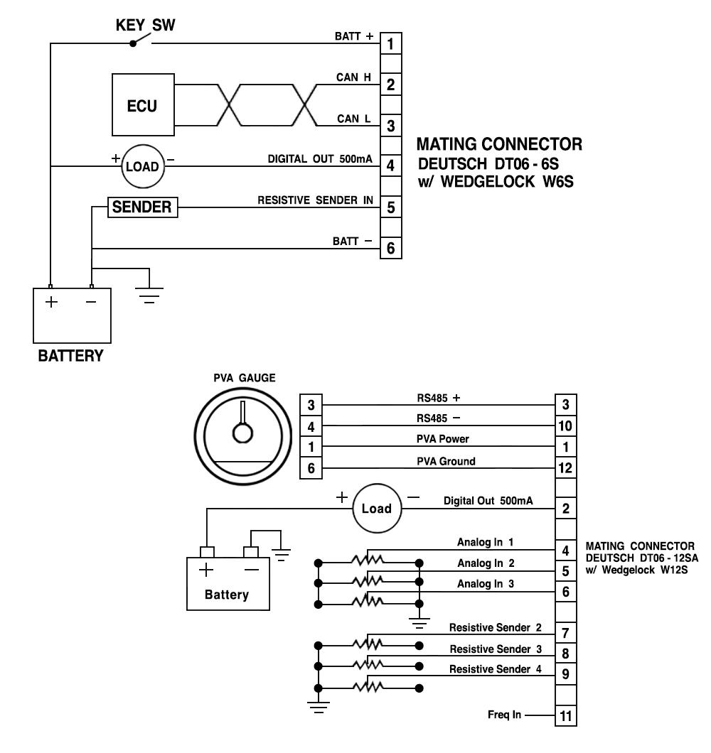
To wire the magnetic sensor pickup use 18 awg 10mm twisted pair shielded cable. Allow a few inches of extra wire service loops for ease of servicing.

Sales Bulletin 00072 Revision Date A 03 2013 Murphy
Murphy gauge wiring diagram. The 20p series 2 inch51 mm dial and the 25p series 2 12 inch64 mm dial swichgage models are diaphragm actuated pressure indicating gages with built in electrical switches. We didnt make them so popular our customers did. Theyre highly accurate and long lasting. Hdrgagessmalljpg fw murphy is known for its gauges and theres a good reason why. Determine voltage and polarity of the application before wiring the unit. The eg21 series electric gage and the egs21 series swichgage instruments take the electric gage to new heights with proven state of the art technology and reliabilitythe egs21 series swichgage instrument has all of the features of the eg21 series gage plus an adjustable set point powerhall effect switch output for operating alarms or equipment shutdown.
These switches are used for tripping alarms andor shutdown devices. Murphy wd 8198b wiring diagram wd100 series panels wd100 wd150 wd175 wd185 518ph tattletale magnetic switch with mechanical swichgages this is a basic energize to run panel. Powerview model pv450. Typical wiring diagrams in order to consistently bring you the highest quality full featured products we reserve the right to change our specifications and designs at any time. We just make them solid and reliable every time. Call your sales representative or fw murphy for more information.
Use the appropriate wire size. The egs21 electric swichgage takes the electric gauge to new heights with proven technology and reliability. Utilizing murphys proven eg air core movement design the egs series offers technological improvements in overall operation lighting accuracy in reading wiring and installation. 00 02 0732 2016 02 26 section 78. Installation and operation manual. 760af 15 12 time delay where applicable.
It will keep power on from the nc terminal to your run circuit unless you have a safety condition on oil pressure or coolant temperature. Base models 117 117ph 518ph 518aph 760a in line fuse available 822ph m42641cd ms2100 ms2111 ms2110 ms2120 add letter f to base model to indicate an in line fuse instead of a base mounted fuse. Typical wiring diagrams figure 2 shows a closed loop circuit with normally open murphy swichgage and v. Use insulated crimp on solderless ring type wire terminals. Theyre durable and dependable. Typical wiring diagram with 760a and 761aph g no r nc sw1 sw2 b 518ph jumper b sig grd distributor ignition coil fuel valve rack pull solenoid rp2300 series shown tachometer hourmeter closedloop wiring voltmeter 20t f temperature 20p f pressure ammeter battery st acc ign bat start switch alternator to magnetic sensor.
Gallery of Murphy Gauge Wiring Diagram