Mitsubishi electric programmable controlle rs must be installed in control panels. Easy to confirm the connection condition 2.

Resistors Wiring Diagram Symbols Diagram Symbols
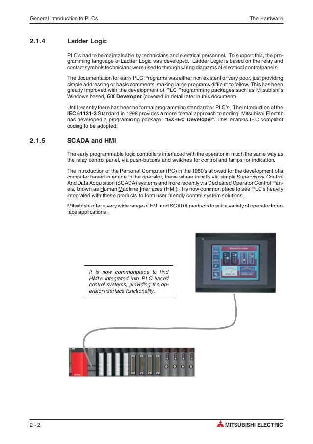
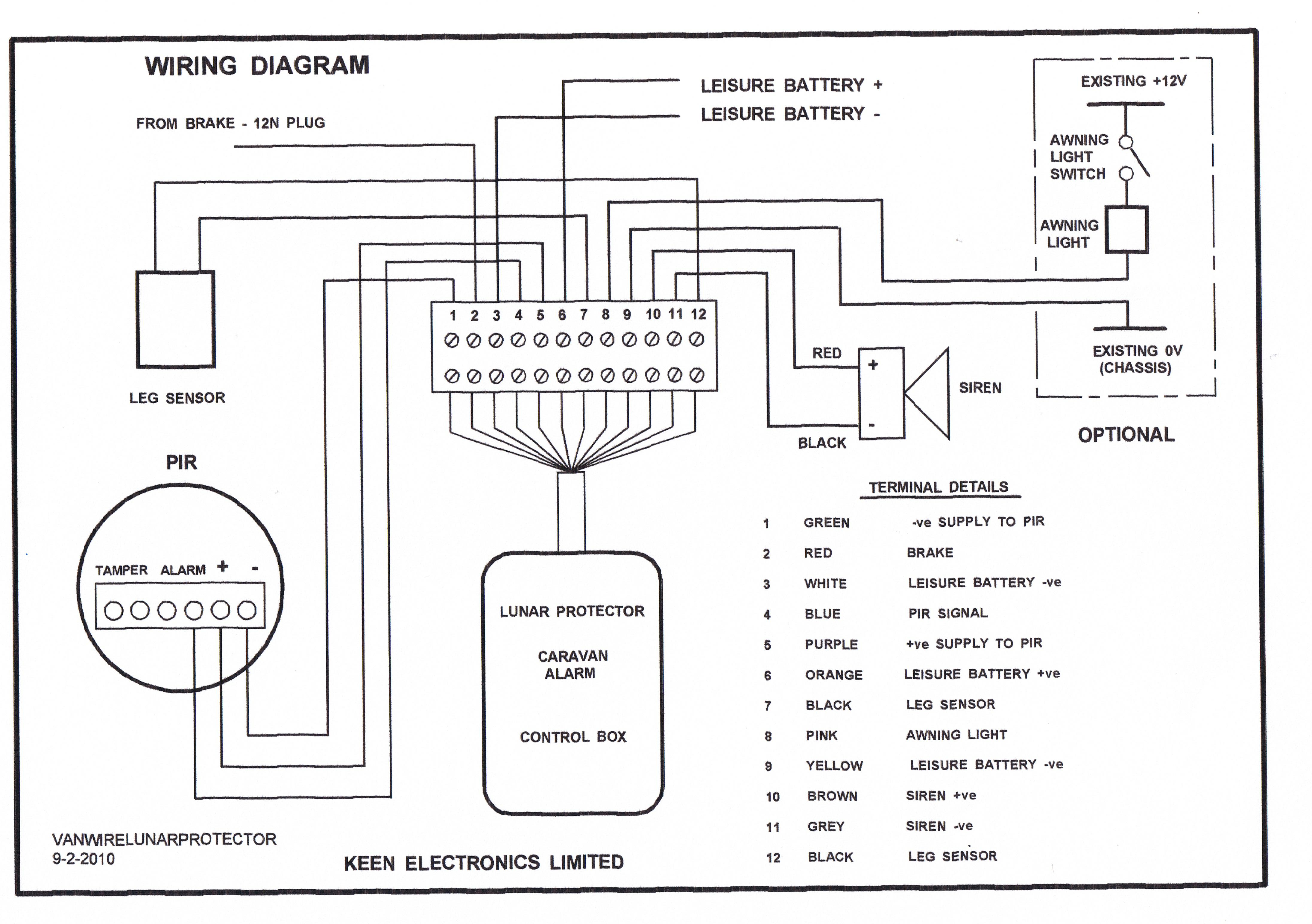
Mitsubishi qy10 wiring diagram. Mitsubishi qy10 q series 16 point relay 240 vac24 vdc 2 a contact 16 pointsco mmon. Reduced wiring and maintenance time with fluorescent indicators wiring connections can be easily confirmed. Mitsubishi montero 2003 circuit diagrams 4. View and download mitsubishi qx10 user manual online. Connect the main power supply to the power supply module in the control panel through a relay terminal block. Impervious to vibration secured wiring connections.
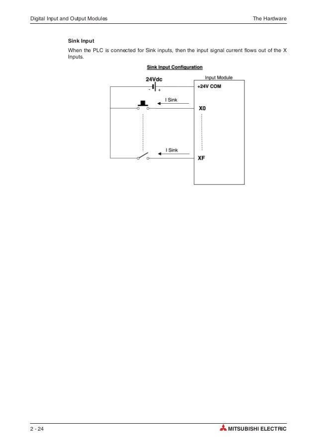
Io module type building block. For the wiring methods refer to the qcpu users manual hardware design maintenance and inspection startupmaintenance instructions. Wiring and replacement of a power supply module must be performed by qualified maintenance personnel with knowledge of protection against electric shock. Qy10 ts qy40p ts qy80 ts spring clamp terminal block type output module mitsubishi programmable controller features 1. Furthermore the wiring and replacement of a power supply module have to be performed by a maintenance worker who acquainted with shock protection. Qx10 controller pdf manual download.
Mitsubishi montero 2003 circuit diagrams 1. Mitsubishi montero 2003 circuit diagrams 2. Mitsubishi montero 1998 wiring diagram. Danger do not touch the terminals while power is on. 3 output module specifications melsec q 3. Output module specifications 31 qy10 contact output module type contact output module specifications qy10 appearance number of output points 16 points isolation method relay rated switching voltage 24vdc 2a resistive load point 8acommon current 240vac 2a cos minimum switching load 5vdc 1ma.
Mitsubishi montero 2003 circuit diagrams 3. Mitsubishi montero 1983 85 wiring diagram.
Gallery of Mitsubishi Qy10 Wiring Diagram