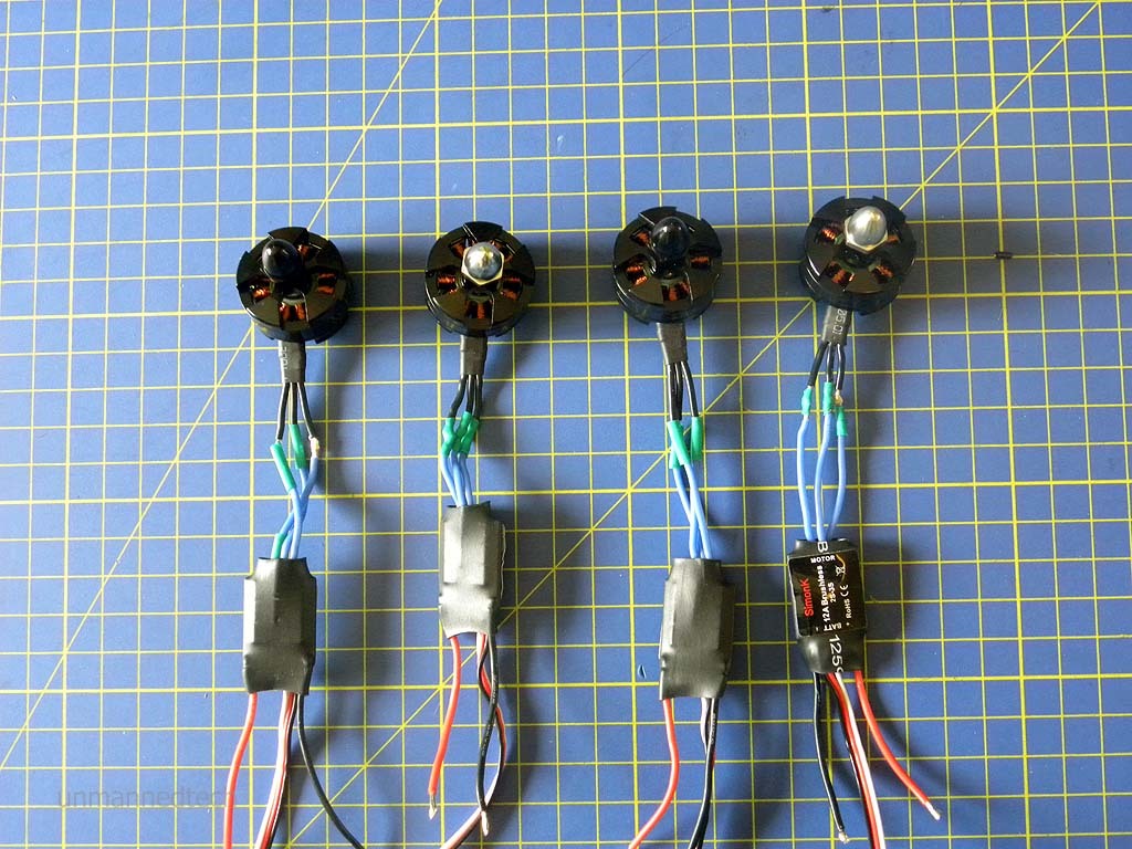
The best way to get perfect wire lengths is to solder components when they are already in place on the drone. The emax rs series claim that changing from a 22 gauge to a 20 gauge wire increased the power output by 5.
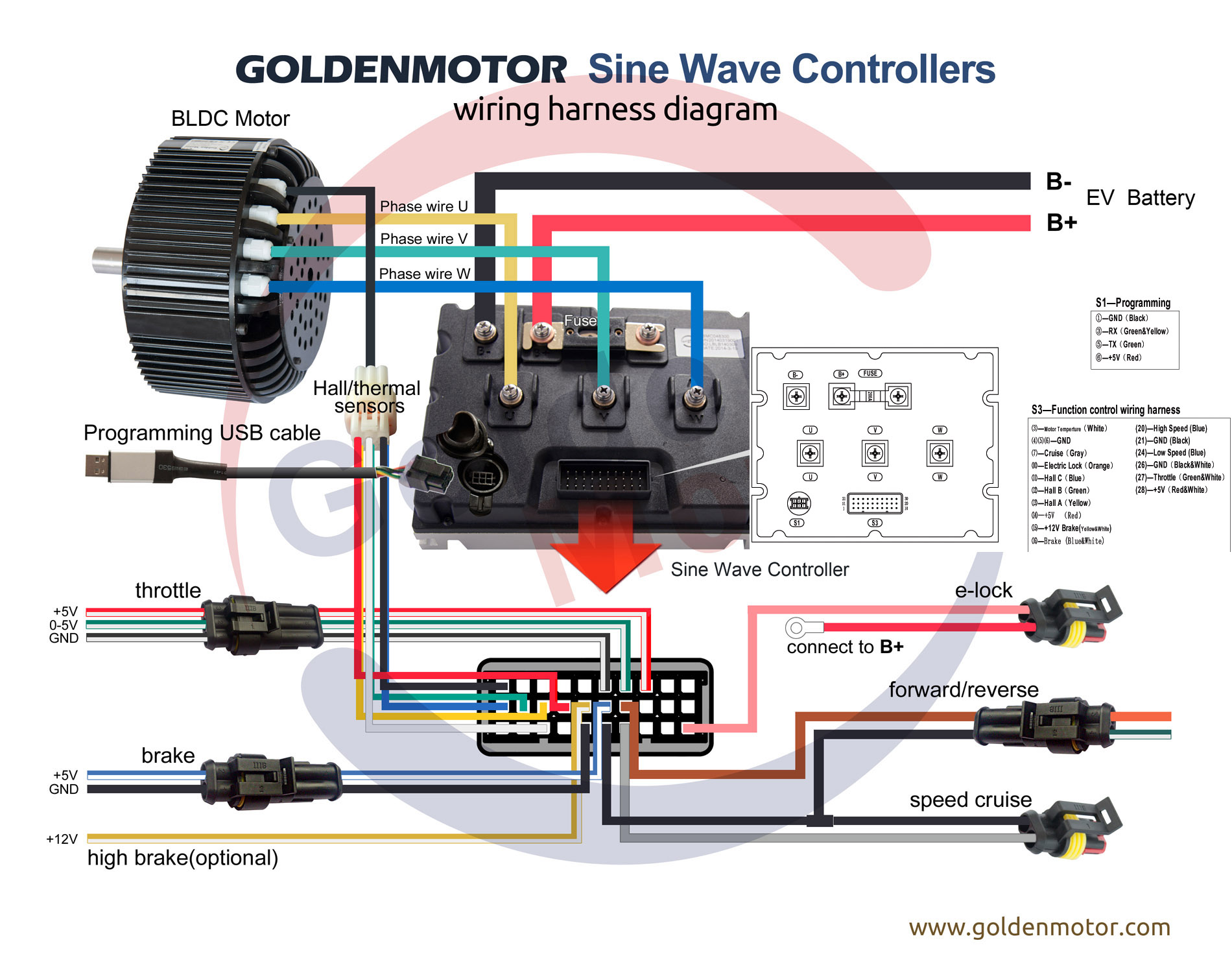
Brushless Motors Bldc Motor Sensorless Motor Motor
Drone motor wiring diagram. The kv rating of a motor. Osd and transmitter and camera and battery wiring diagram. The order in which you connect the esc is important. The next thing that affects the performance of a motor is the wire gauge of the motor. How to choose electrical wires for fpv drones wire thickness resistance and current rating resistance is proportional to the electrical. Basically cw clockwise and ccw counter clockwise motors are still the same motors apart from the prop shaft threads which have opposite.
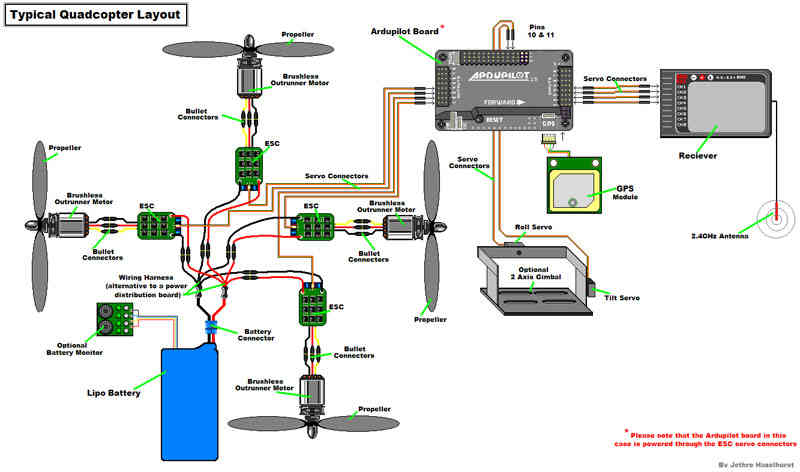
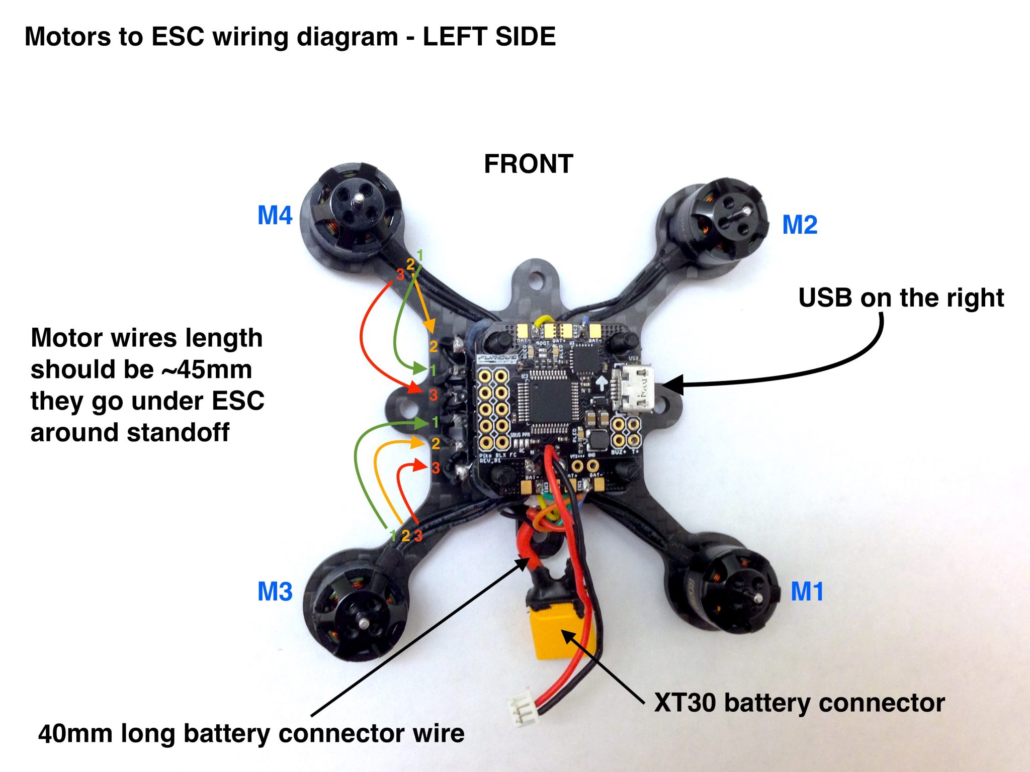
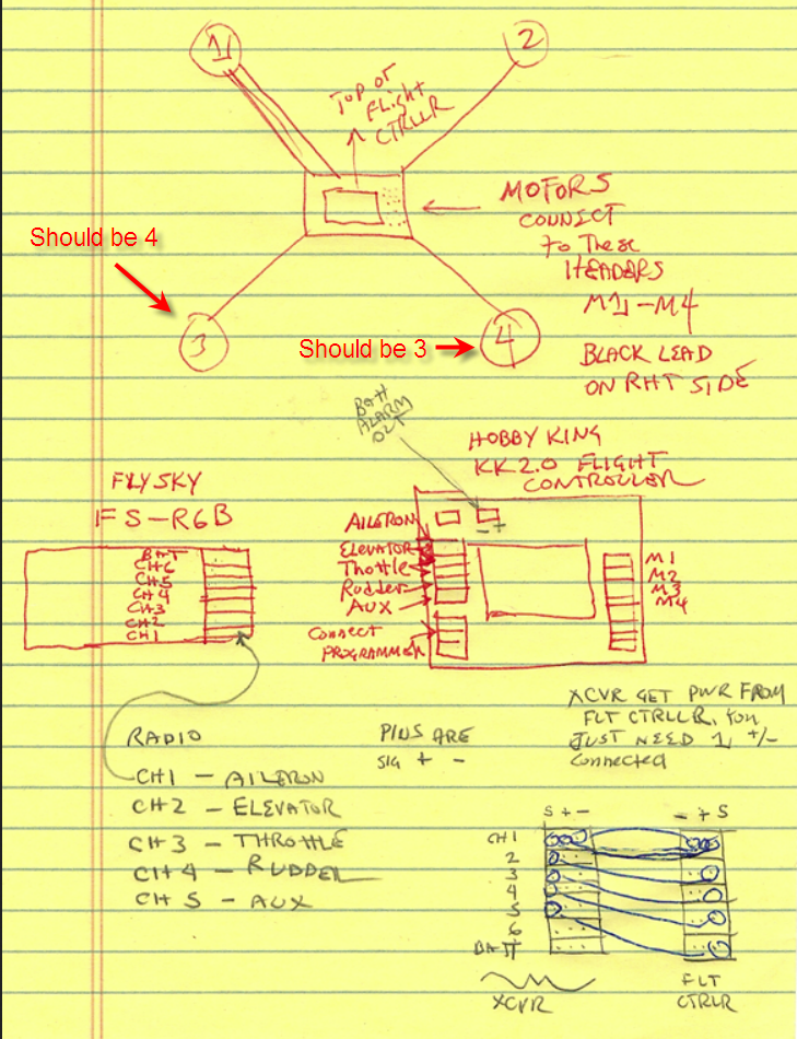
This increase of speeds can be enforced by configuring the remote control relays as per the following wiring diagram. A drone wiring diagram is a simple visual representation of the physical connections and physical layout of an electrical system or circuit. Drone wiring diagram detail. Referring to the above diagram we realize that we simply need to appropriately increase the speeds of the relevant motors for executing the desired directional maneuvers on the drone. They reduce weight and improve the neatness of the craft. You will need to connect motor 1 of your drone to motor connector 1 and motor 2 to connection 2.
When a motor is supplied with a voltage it spins. Some mini quad motors are labelled cw and ccw and it can cause a hell of a confusion for a lot of people in this hobby including experienced quadcopter builders. Typical fpv racing miniquads will use 1806 or 2204 motors whereas larger quadcopters that are designed to carry a gopro camera will typically be around the 2212 size. This article explains why and how wire and connector size can affect the performance of your fpv drone aka quadcopters. We can split the base drone wiring diagram into multiple parts as below. Race wire replaces long motor wires to the esc.
But this is no big deal when buying a motor and getting started in the hobby. In this guide we hope to answer some of the questions with easy to understand diagrams. Wires should have some slack so as not to put tension on the solder joints. Gps wire from compass m1 motor no1 m2 motor no2 m3 motor no3. Using the ground wire is not absolutely necessary but is highly recommended as its best practice to ensure all the electronic devices have a common ground so if you can just connect it. Flight controller connection wiring diagram.
The motors either use 20 awg or 18awg american wire gauge. I need help with wiring diagram or photo of the flight controller. Under the splash drone discussion section. It shows how the electrical wires are interconnected and. I have two wires from com 1 that have the pins slipped out of the plug to the main board. As you see above the base of drone wiring diagram there are so many components are need to connected with each others.
I will recommend some places where you can get these battery connectors and wires from. Use race wire with 4 in 1 escs. The size of the motor can give you an idea about what size drone you will use with the motor.


