Incremental comfort conditioners suite ii with top mounted hydronic heat section. Warranty 01995 mcquay international.
109ee219 Mcquay Heat Pump Wiring Diagram Digital Resources
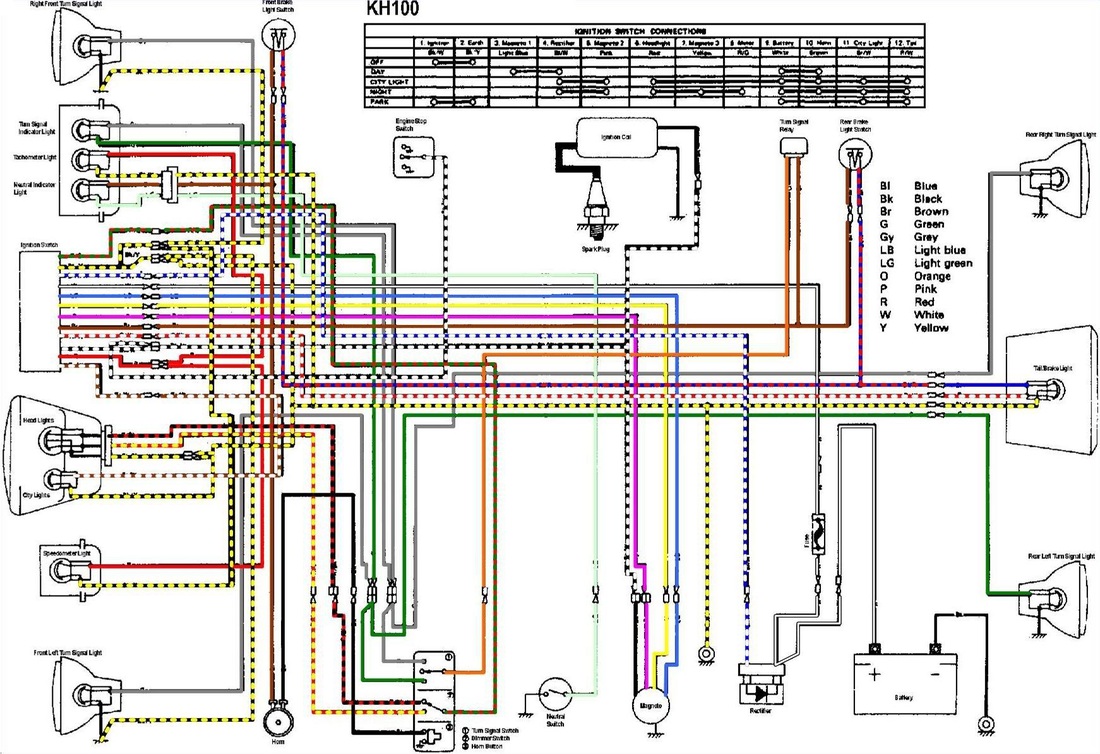
Mcquay wiring diagram. Are options available only with the premium control board. Ceiling concealed chilled water fan coil unit. Figure 37 page 28 or the units wiring diagram which is mounted mcquay thermostat or control. Typical wiring diagrams. Be sure to use the specified cable for wiring between the indoor and outdoor units. Field wiring diagram58 system maintenance60 p reventative m aintenance s chedule 63.
Im 934 2 applied pdaapdha page 37 of 44. Internal wiring regulations and the instruction manual for installation when conducting electrical work. Catalog 604 3 magnitude magnetic bearing centrifugal chiller model wme 400 to 700 tons 1400 to 2461 kw 360460 hfc 134a. It can also be used in attached to the corner panel on cabinet units and to the chassis conjunction with a controller of a building automation system front cover on hideaway units. Field installed options on microtech units maintenance troubleshooting. Mcquay enfinity water source heat pumps catalog 1100 horizontal features and benefits low design and installation costs four configurations for each unit size left or right re turn and straight or end discharge allow you to specify.
Cch ceiling concealed water source heat pump ccw ceiling. View and download mcquay mcw200 technical manual online. Typical wiring diagrams figure 8. Ptac 106018561 air conditioner pdf manual download. Mcw200 air conditioner pdf manual download. Information covers the mcquay international products at the time of publication and we reserve the r ight to make changes in design and construction at anytime without notice.
Mcw300 mcw1000 mcw1200 mcw400 mcw600 mcw800. The gray tinted areas in the wiring diagram. 2009 mcquay international. Options for mark ivac units. Insufficient power circuit capacity and improper electrical work may cause an electrical shock or fire. For the latest drawing version refer to the wiring diagram located on the inside of the controls access panel of the unit.
Cch 024c g s model type mcquay brand. Typical mark ivac wiring diagram ground component layout compressor contactor fan contactor transformer compr pc board motor auxiliary relay circuit breaker heater 070 blk 060 blk 048 red motor 042 blk 036 blk. View and download mcquay ptac 106018561 installation maintenance data online.
