Operating your windlass 9 31 safety fi rst 9 32 use of clutch 9 33 letting go under gravity 9. Use diagrams a or b atlantic b concept ocean2.

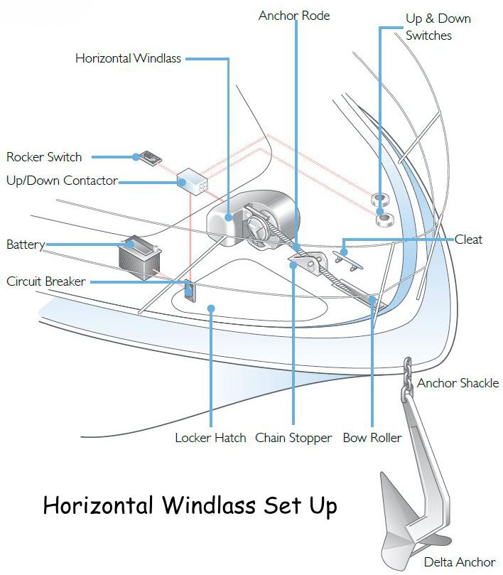
Windlasses Amp Rollers West Marine
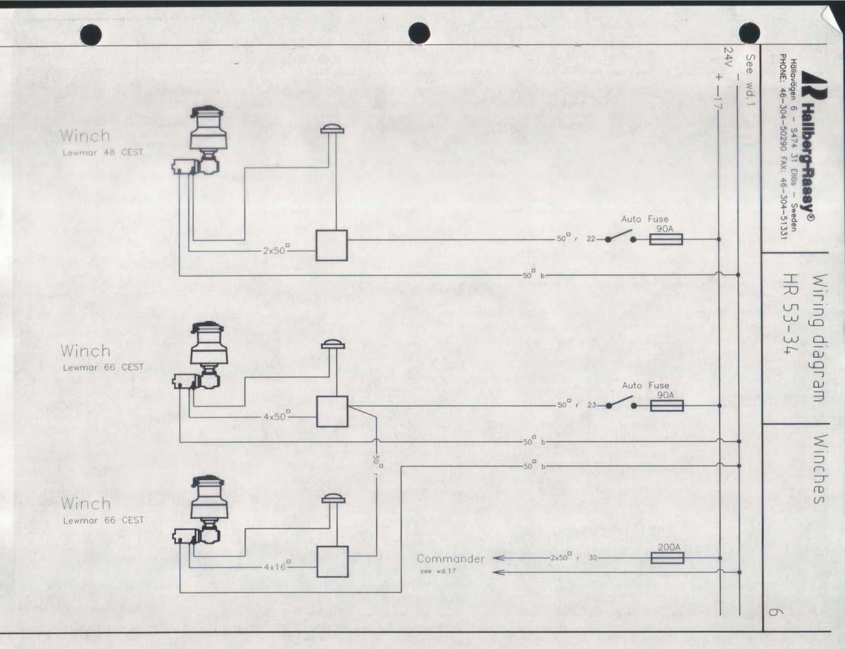
Lewmar windlass solenoid wiring diagram. It reveals the components of the circuit as simplified shapes and the power and signal links in between the devices. Collection of windlass wiring diagram. 16 fitting the windlass to the deck 5 2. 44 0 23 9248 5720 tech support email. Sprint 900 atlantic atlantic a atlantic c ap700 ap1000 ap1200. A wiring diagram is a simplified standard photographic depiction of an electric circuit.
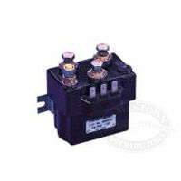
Wiring diagram 12vdc used on. Electrical wiring installation 7 21 electric cable selection 7 22 wiring 7 23 control switch installation 7 24 v700 wiring diagram toggle switch 8 25 v700 wiring diagram contactor 8 3. Lewmar windlass solenoid wiring diagram 10092018 10092018 3 comments on lewmar windlass solenoid wiring diagram here well discuss windlass solenoids or what they call a windlass control box usually youll have to completely remove the control box and disconnect all wires. Use diagrams c or e contactor 0052531 is not suitable for these products. Anchorman power serial prefix 450. 44 0 23 9247 1841 fax.
Lewmar limited southmoor lane havant hampshire po9 1jj united kingdom. Can be used with all lewmar custom windlasses contact the sales office for a specific wiring diagram. Closest direct replacement v2. To thruster solenoid loom 3 4 1 2 grey blue red black grey black 3 blue ack 2 red black 1 b lack grnye 54321 5 button wireless receiver module 68000968 876 for terminals 1 to 5 refer to windlass wiring di agr ms. Use diagrams c or d sprint 3000.
Gallery of Lewmar Windlass Solenoid Wiring Diagram