Turn both a and b on step 2. Wiring diagram below to properly connect your wires to the insteon device note.

For Wiring Up A Smart Home Insteon Micro Open Close
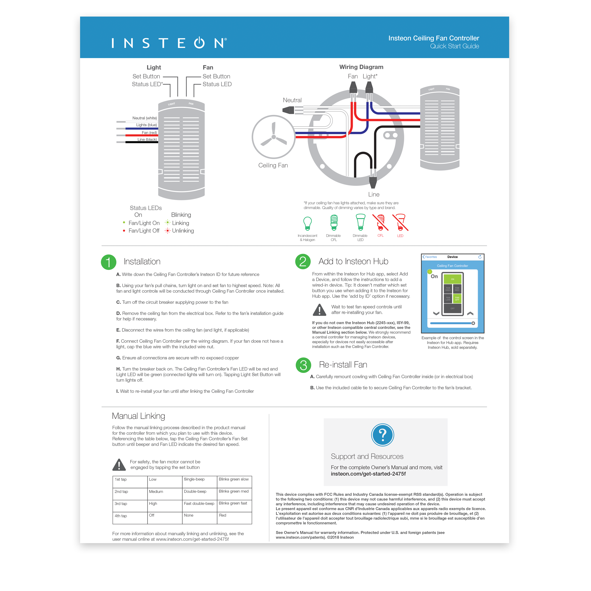
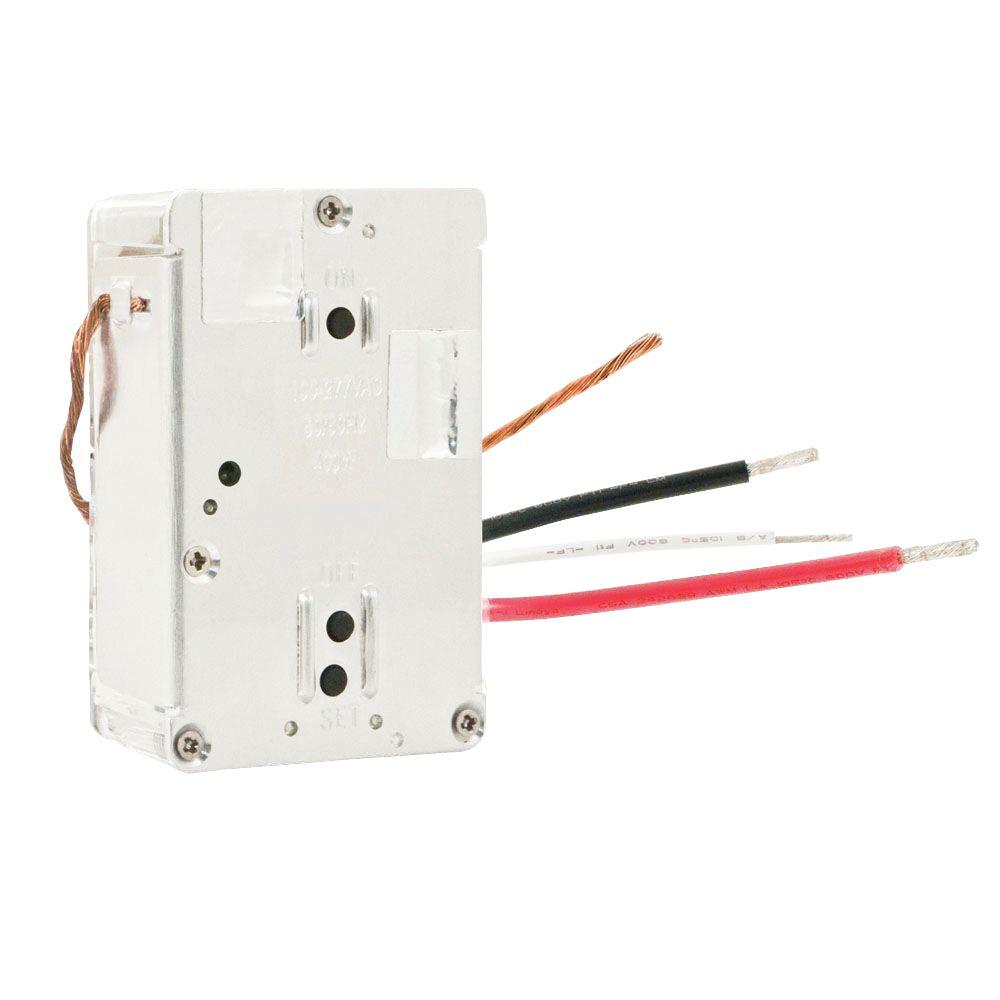
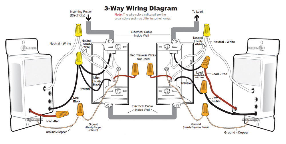
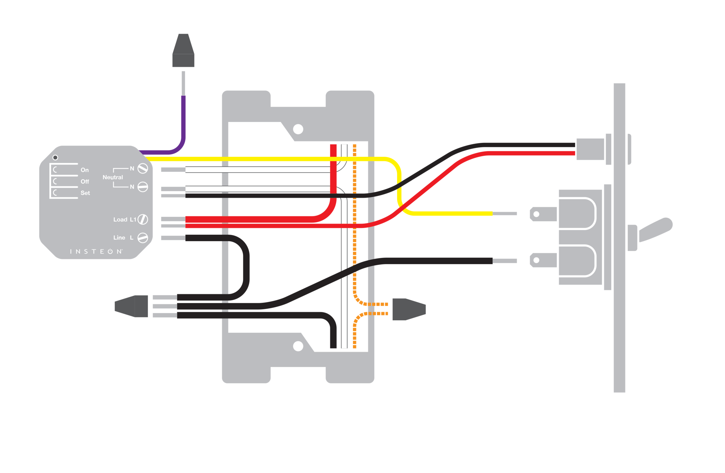
Insteon wiring diagram. Mechanical switches dont utilize neutral wires but they are usually available in the back of the switch box. A wiring diagram is a kind of schematic which makes use of abstract photographic icons to reveal all the interconnections of components in a system. Icons that represent the elements in the circuit and lines that stand for the links between them. Turn off power and connect the corresponding wires from the junction box with the insteon wall switch and cap them with wire nuts. 3 way linking step 1. If your switchs wires do not match the diagram consult the additional wiring diagrams available below.
Press and hold bs set button down until it double beeps a will double beep and its led will stop blinking a is. Press and hold as set button down until it beeps as led will start blinking step 3. Insteon 2 way switch wiring diagram steppng if your switchs wires do not match the diagram consult the install insteon wall switch attach the wal plate and turn on power. Turn on power and use a voltage detector to identify the live wire. With both switches still on press and. This is your line wire.
This is your line wire. Turn off power and connect the corresponding wires from the junction box with the insteon wall switch and cap them with wire nuts. Turn on power and use a voltage detector to identify the live wire. Circuitry layouts are composed of two points. Insteon provides the following wiring diagram for installing a 3 way the two switches together can the secondary switch affect the power flow. If your switchs wires do not match the diagram consult the additional wiring diagrams available below.
Gallery of Insteon Wiring Diagram