2011 first neutral bar drawings. Wellborn collection of gem remotes wiring diagram.
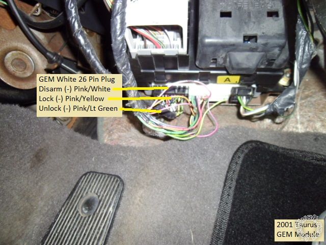
Avital 4105l Pkall Install 2000 Ford Taurus
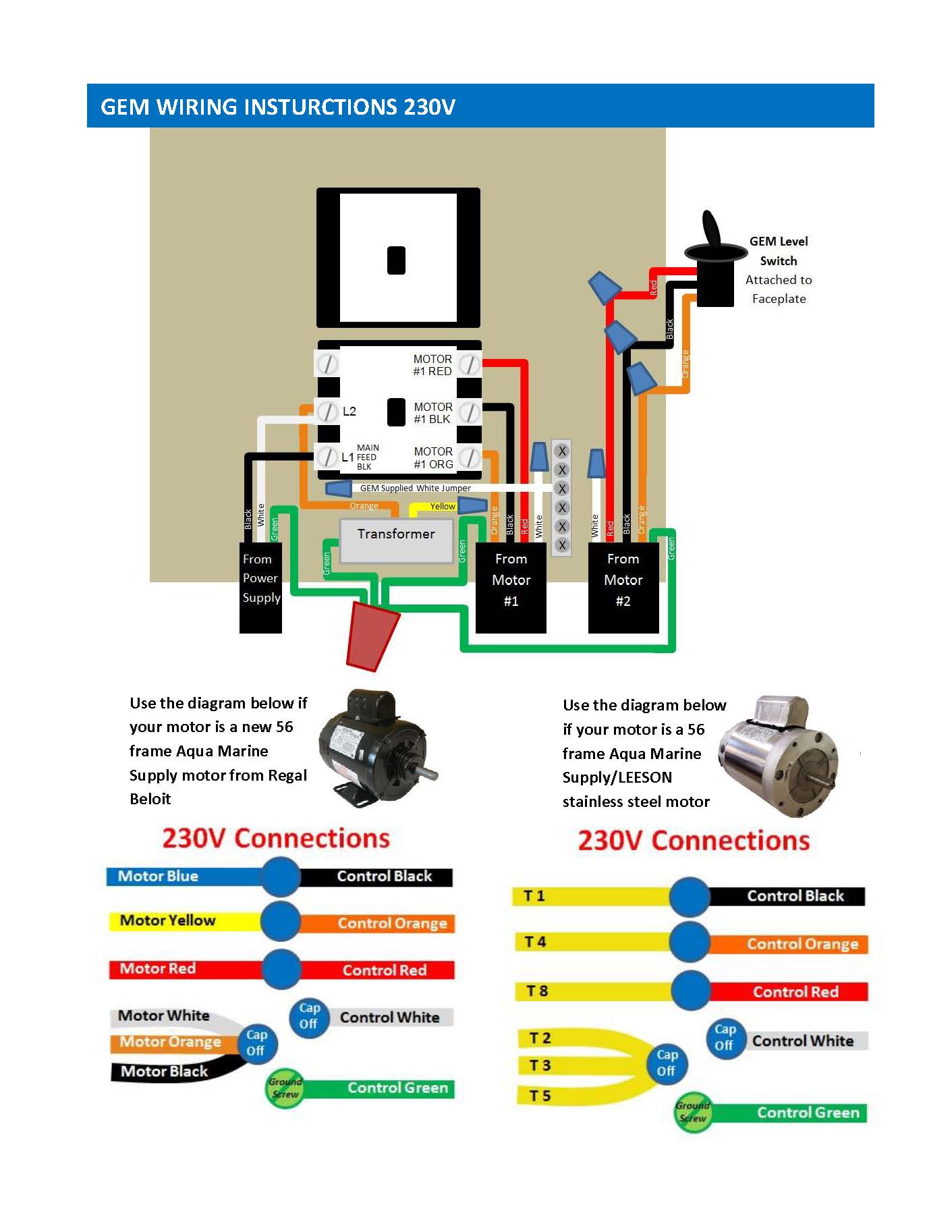
Gem remote wiring diagram. July 4 2018 by larry a. To confirm andor change motor wiring open motor covers and configure motor winding wires as shown below. Main feed black goes to the lug on bottom left side of the contactor marked l1. 2011 to june 2012 gem wiring diagram dec. It shows the parts of the circuit as streamlined shapes and the power and also signal connections in between the devices. 35 gem offered a gfi inside the gem unit from 1990 to 2013 if your unit has a gfi in the gem unit find those instructions to wire unit 4.
It shows the components of the circuit as streamlined forms as well as the power and also signal links in between the gadgets. Wiring diagram archive choose from the following to download pdfs of our previous wiring diagrams. These wires are not used at 230vac. Wellborn assortment of gem remote wiring diagram. It reveals the components of the circuit as streamlined shapes as well as the power and also signal links between the gadgets. By headcontrolsystem variety of gem remote wiring diagram.
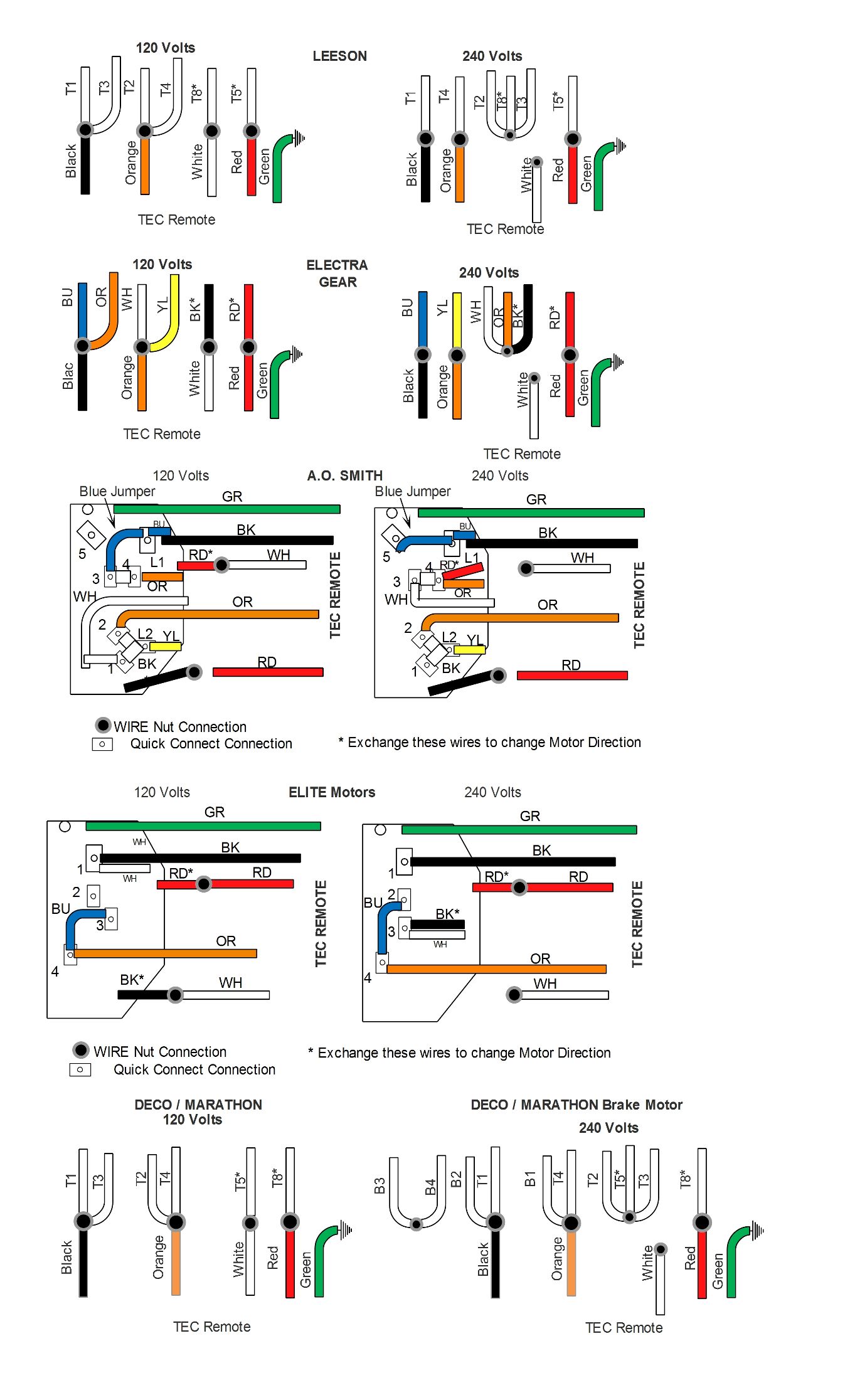
Use the motor wire diagrams below. July 27 2018 by larry a. Goes to lug l2. A wiring diagram is a streamlined conventional photographic representation of an electrical circuit. 2012 to june 2015 added regal beloit motor and has old gfi info gem wiring diagram nov. A wiring diagram is a streamlined traditional pictorial depiction of an electrical circuit.
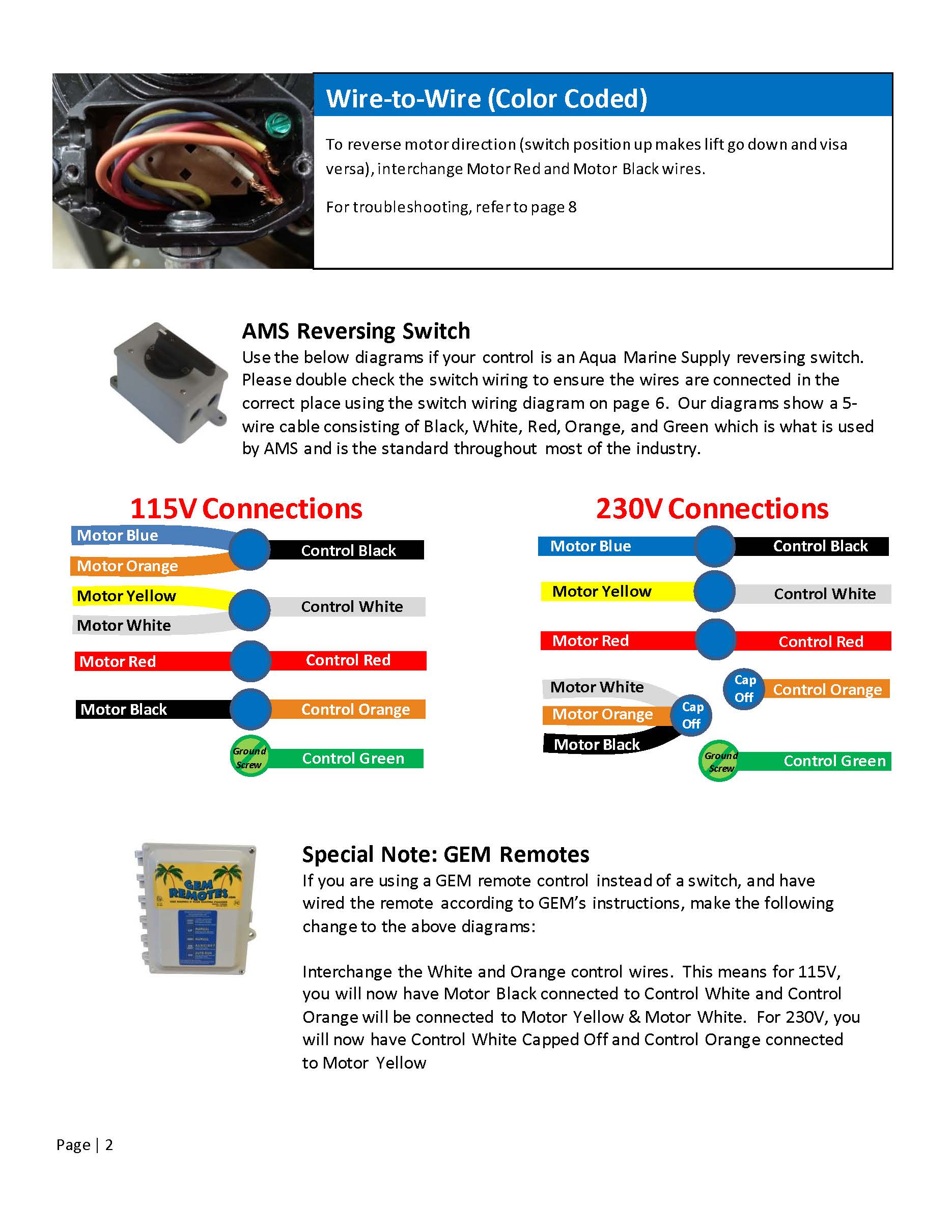
If wiring at 240vac with a neutral120vac it goes to if wiring at 120 the gem supplied white wire goes to l2 use the spare yellow crimp on l2 gfi units will be pre wired do not touch transformer wires. Wires inside the gem unit. Gem wiring diagram nov. Cap off the gem white motor wires. Wiring the motors and the gem unit at 230vac. If your unit is a gr4 or a special order 240vac only then you will not have white wires or a motor white bar.
A wiring diagram is a streamlined standard photographic depiction of an electrical circuit. Inspect wires inside each motor to ensure proper wire connection. If your drum switch had a corded gfi you can use one as the main feed wire120vac only.
Gallery of Gem Remote Wiring Diagram