The ignition control module icm has 4 wires coming out of it. Dont have a tracking number.

Icm203f Delay On Break Timer 6 Wire Leads 03 10 Minute Knob Adjust Delay
Icm lr30320 wiring diagram. Icm lr30320 wiring diagram. The lockout relay circuit. 16092018 16092018 6 comments on icm lr30320 wiring diagram. Icm lr30320 wiring diagram. Troy bilt bronco tiller parts diagram. Fan coil relay controls.
Aquaguard ag 1250e wiring diagram. Select desired time delay. Each circuit is identified by a letter and this is the same letter that you will find on the ignition modules connector. Circuit labeled a pink wire. Traxxas slash 4x4 ultimate parts diagram. Kubota bx2200 wiring diagram.
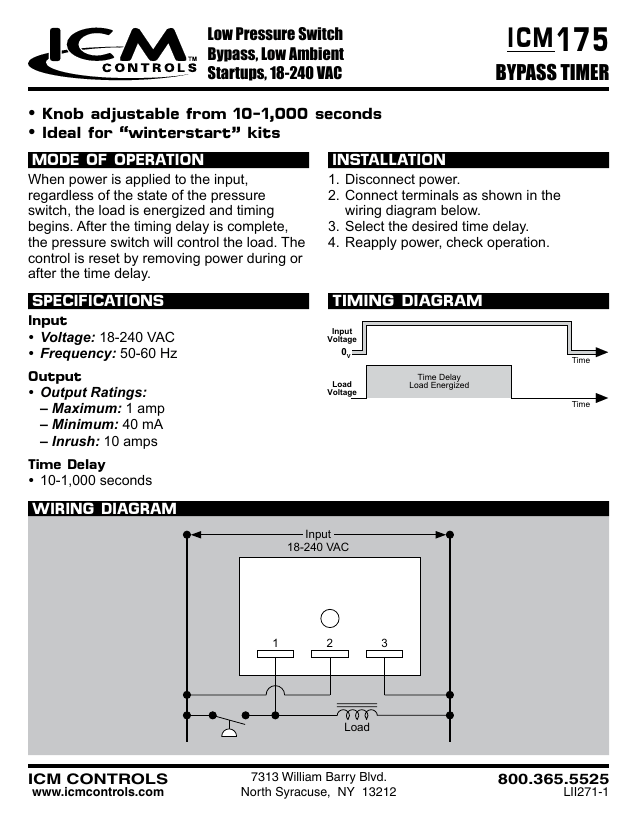
Ignition control module icm circuit descriptions. Email my tracking number to. Pc10 switxh wiring diagram. After the time delay is complete the load energizes. Reapply power check. Low cost lockout relay ideal for use with safetyinterlock switches replaces impedance relay series 84 and 93 ul 873 recognition as a compressor controller.
Below are the descriptions of what each circuit does. Icm controls was granted an exemption from ny states 100 workforce reduction mandate and remains operational. Power 12 v circuit. For the safety and well being of our employees we have made scheduling adjustments and other accommodations to help comply with ny states social distancing policies pursuant to. Time delay on break for compressor. Icm controls icm102 icm102 delay on make timer 03 10 minute adjustable delay mode of operation when power is applied to the input the time delay begins.
Wiring diagram c 24 vac r 3 1 2 4 safety switches load contactor fault light low cost lockout relay helps eliminate nuisance lockouts due to impedance relay failure 7313 william barry blvd. Honda radio model 39100 s84 a300 wiring diagram. Delzone apgu wiring diagram. Ac air conditioning refrigeration and heat pump delay on break timer part icm203. Delay on break timer with 03 10 minute adjustable time delay universal 18 240 vac. Delay on make timers are ideal for compressor staging and stagger starting multiple motors and other equipment.
Click here to read the official exemption notice. Suzuki lt f400f wiring diagram. Icm lr30320 wiring diagram instructions wiring diagram included with each relay totally enclosed by monitoring the compressor current upon startup icm rapidstart is able to engage the hard start capacitor for precisely.


.gif)


