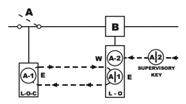
Key a 2 can be turned to extend the bolt of the l c interlock into its recess which locks the device in the closed position. 3 double pole double throw dpdt auxiliary switch.

Skru Manual Kirk Leader In Trapped Key Interlock Solutions
Kirk key interlock wiring diagram. Download the specific product datasheets for the following product informationoperation usage installation maintenance technical data application information dimensional drawings ordering information. Tdkru wiring diagram 235 162 notes. This releases key a 2 from the l c interlock. Pts électrique ltée 2012 2020. The skpm is designed to permit removal of the interlock key in response to an. 3 auxiliary switch is open.
4 kirk key interlock with key normally trapped in lock. 4 signal lamp is de energized. 20201 av clark graham baie durfé qc h9x 3t5 514 457 8886 toll free. Key removable when solenoid is energized. 1 key a 2 is out of interlock. Meanwhile key a 1 is held in the l o interlock since its withdrawn locking bolt cannot be extended.
Kirk solenoid panel mounted the skpm consists of a keyed interlock a solenoid and a pair of auxiliary switches 2 no. 1 circuit a input 2 customer to wire this side only. 2 key a 3 is held in interlock. Skru wiring diagram 156 649 notes. 1 signal lamp 5 terminal block 2 solenoid 6 power source 3 kirk key interlocks 7 timing relay 4 auxiliary switch normal operating conditions. Circuits 3 4 6 7 are closed and circuits 4 5 7 8 are open when the key is trapped in the interlock.
Gallery of Kirk Key Interlock Wiring Diagram