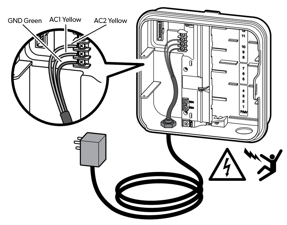
Connecting a pump start relay. Connect the wires to the ac terminal block inside the junction box.

Zx 6006 Kawasaki Mule 2510 Wiring Diagram Kawasaki Mule
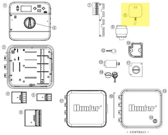
Hunter xc wiring diagram. Verify station fault remove the field wire for the faulted station. X core components 4 lcd display 1 run times allows user to set each valve station run time from 1 minute to 4 hours 2 start times allows 1 to 4 start times to be set in each program 3 station number indicates currently selected station number 4 program designator identifies program a b or c in use 5 day of the week identifies day of the week 6 interval watering identifies month when. Check valve wiring check the electrical resistance within the field wiring circuit for the defective zone. Attach a separate control wire to the remaining master valve installed in your irrigation system. Helpful information about wiring mounting options downrods and more. A hunter weather sensor or other micro switch type weather sensors can be connected to the xc.
Wiring an irrigation solenoid valve duration. Complete this section only if you have a pump start relay installed. This is video 2 of a 3 part series. If the err message is not present the problem is with the valve or field wiring. A pump start relay is a device that uses a signal from the controller to actuate a separate electrical circuit to energize a pump to provide water to your system. For e models only.
You can manually test proper operation can be connected to the xc. Ac supply wires must be 14 awg 185 mm or larger with appropriate circuit breaker for the wire size. Connect one wire to one sen terminal and the other wire. At the master valve attach the common wire to either solenoid note. The ground wire should be connected to the green wire. Access irrigation ltd.
This video is for hunter xc and hunter x core lawn irrigation controllers. Connecting a master valve 1. The battery allows the user to remotely nal screw. Complete this section only if you have a wire of the valve. Remove the metal jumper plate that is attached across the two sen terminals inside the controller. Tighten each termi xc controller.
Most sprinkler timers will be similar to this example. Terminal strip area use to attach transformer and valve wires from area shown in the diagram. Program the controller without connecting ac power. Wiring or 3 poor wire connections. Wire nuts are provided to make these connections. Start the controller manually.
The controller should be mounted at least a 15 ft 45 m away from both the pump start relay and pump to minimize any potential electrical interference. 5below is a typical drawing and description of a hunter src series timer masterpump valve wiring. The purpose of this sensor is to stop automatic watering when weather conditions dictate. Connecting a weather sensor a hunter weather sensor or other micro switch type weather sensors wired into the sensor circuit.
Gallery of Hunter Xc Wiring Diagram