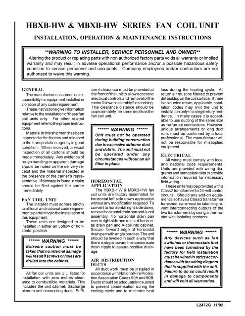
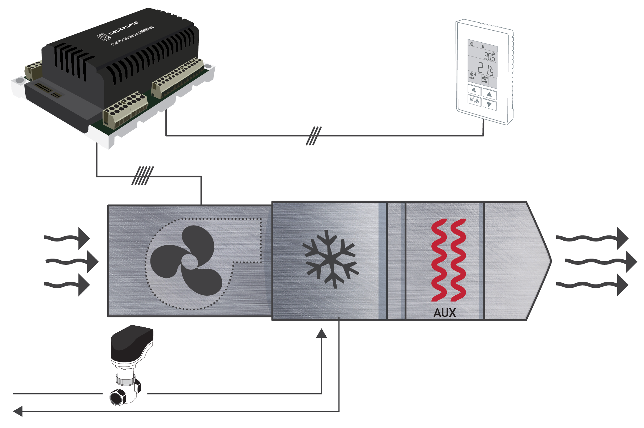
All units with or without electric heat are cetl listed and labeled. All electrical wiring must not touch the water piping or any moving parts of the fan motors.
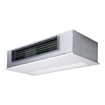
Fan Coil Unit Coolers
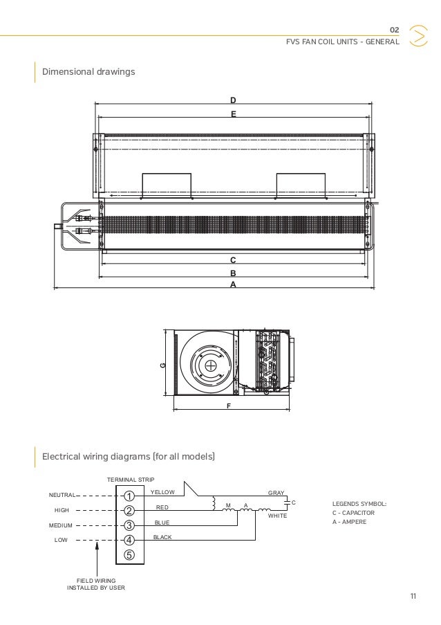
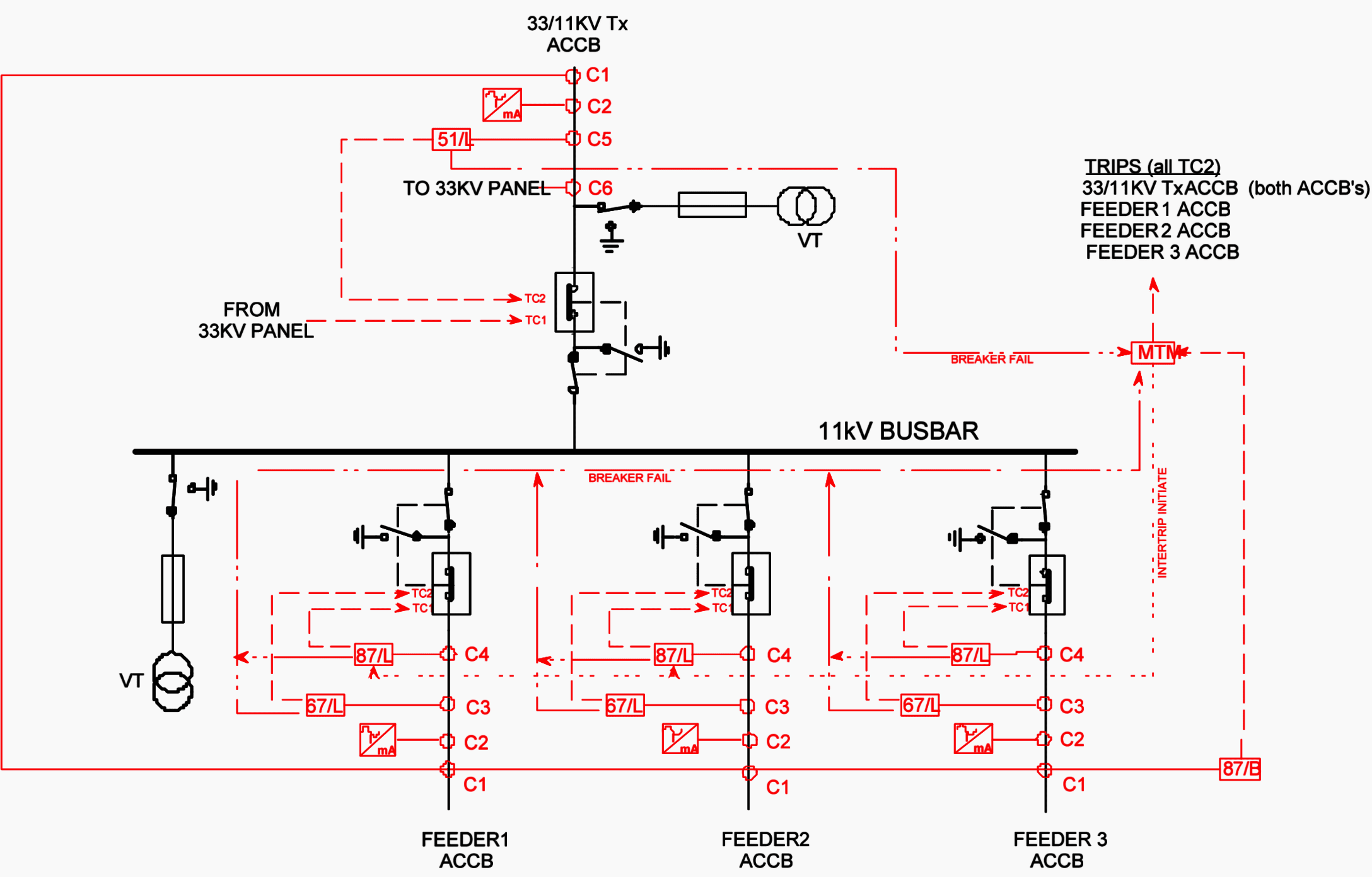
Fan coil unit wiring diagram. If any of the original wire as supplied must be replaced use the same or equivalent type wire. Ensure that the rated voltage of the unit corresponds to that of the name plate before commencing wiring work according to the wiring diagram. Athe fan coil unit is controlled by a unit mounted controller provided by mechanical systems controls contractor mscc. Fan coil unit must be secured to the structure using field supplied hardware. Hp series fan coil units have a removable fan assem bly. Use 60 amp class k fuses only for replacement.
Bon a call for cooling the thermostat signals for the heating control valve to modulate toward the closed position. Angle strap down and away from back. If job site voltage is 208v wcp high low fan speed switch may be rewired to increase air speed. 51 for 3 phase wiring 1. Here is a picture gallery about fan coil unit schematic diagram complete with the description of the image please find the image you need. Use copper wire 75ºc min only between disconnect switch and unit.
The entire fan assembly can be removed from the unit and serviced easily on a workbench. 3 speed ac fan running capacitor. Remove screws as directed. Review all tags on unit to determine if shipping screws are to be removed. Installation operation maintenance fn series fan coils supersedes 11524 nom1 1209 form 11524 nom1 511 introduction johnson controls fan coils represent a prudent. Allow a minimum of 24 clearance from access panels.
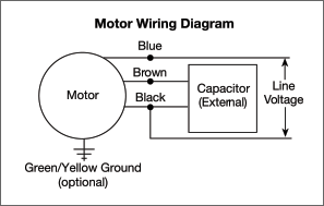
Replace black and red fan motor wire connections with blue and orange fan motor wires respectively. The unit must be grounded to prevent possible hazard due to insulation failure. 10 self tapping screws. Tap must be changed from orange to red. Alfred electronic fan. Identify and prepare units for each unit confirm incoming and control power requirements match available power source.
If fan coil is away from wall attach pipe strap to top of fan coil using no. Refer to wiring diagram located on unit. See unit wire diagram for. When wiring wcp 1830 only. Wiring diagram for carrier fan coil readingrat pertaining to fan coil unit schematic diagram image size 639 x 600 px and to view image details please click the image. Refer to unit nameplate and wiring diagram.
Recommended method of securing for typical applications a. Representative before continuing with unit installations. How to connect the fan wire easy to understand fan coil connector 5 wire condenser fan motor wiring diagram simplest. On a further call for cooling the thermostat signals for the fan to speed up from its. 22 vdc coil r e c red brn label 3 heater va. All wiring is in compliance with nec assuring safety and quality for the owner.
To be wired in accordance with nec and local codes.
Gallery of Fan Coil Unit Wiring Diagram