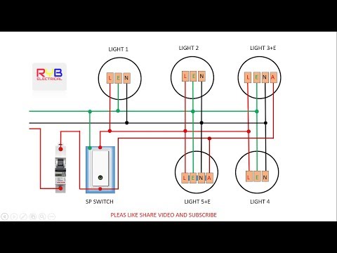
A wiring diagram is a simplified standard photographic representation of an electric circuit. I will put a link to it.
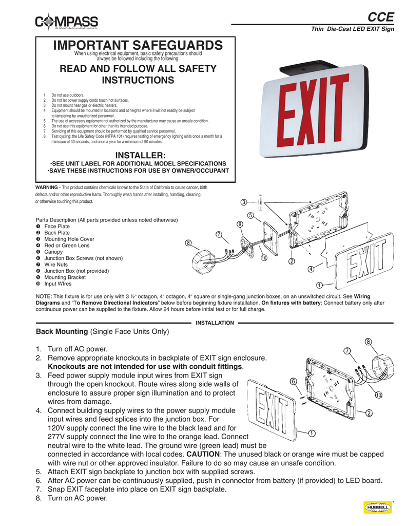
Important Safeguards Compass Lighting Products
Exit sign wiring diagram. Remove proper chevrons as required and replace exit stencil onto housing. A wiring diagram is a streamlined conventional pictorial depiction of an electric circuit. Exit sign wiring diagram a newbie s overview of circuit diagrams a first consider a circuit diagram might be complicated yet if you could read a metro map you can check out schematics. Feed power supply module input wires from exit sign through the canopy. Emergency exit sign wiring diagram whats wiring diagram. Secure back plate to junction box hardware not included.
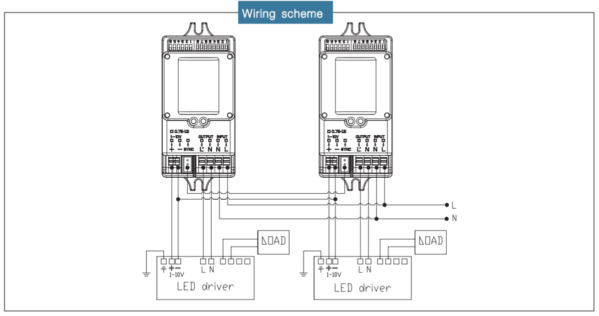
Most exit signs include a mounting canopy which attaches to the side or the top of the unit and mates to a junction box or drywallconcrete as well. Hope this helps everyone who doesnt know how. It reveals the components of the circuit as simplified shapes and the power and signal links in between the devices. Here is a tutorial on how to wire an exit sign or emergency light. A wiring diagram is a kind of schematic which uses abstract pictorial symbols to exhibit all of the interconnections of components in a system. For 120v use black and white wires and for 277v use red and white wires.
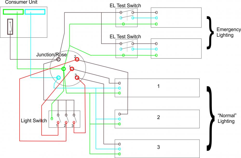
Assortment of emergency exit sign wiring diagram. Connect battery el models only. Route wires along side walls of enclosure to assure proper sign illumination and to protect wires from damage. Combination exits with emergency lights located on the side typically only allow flush or top mount since the heads are attached on the sides and leave no room for the mounting canopy. Literally a circuit is the course that allows power to circulation. A wiring diagram is a simplified conventional pictorial representation of an electrical circuit.
Collection of emergency exit sign wiring diagram. It reveals the components of the circuit as simplified shapes and the power and signal connections in between the tools. Obtaining from factor a to point b. It shows the elements of the circuit as simplified forms and the power and signal links in between the devices. September 1 2018 by larry a. When connected by wiring to a compatible remote head capable emergency light or remote head capable exit sign it provides an efficient means of providing additional lightingin the event of a power failure the remote lamp head will illuminate for 90 minutes just as if it were a separate stand alone emergency light.
Route exit input wires through center hole of the back plate and make wiring connection. Wiring diagrams comprise two things. This is an updated version of one i made a long time ago. Symbols that represent the components inside the circuit and lines that represent the connections with shod and non shod. A remote head is a stand alone lamp with no internal power supply. Secure the canopy to the exit sign enclosure by removing the appropriate mounting hole cover and snapping canopy onto enclosure.
Exit sign wiring diagram. Collection of exit sign wiring diagram. The objective is the exact same.
Gallery of Exit Sign Wiring Diagram