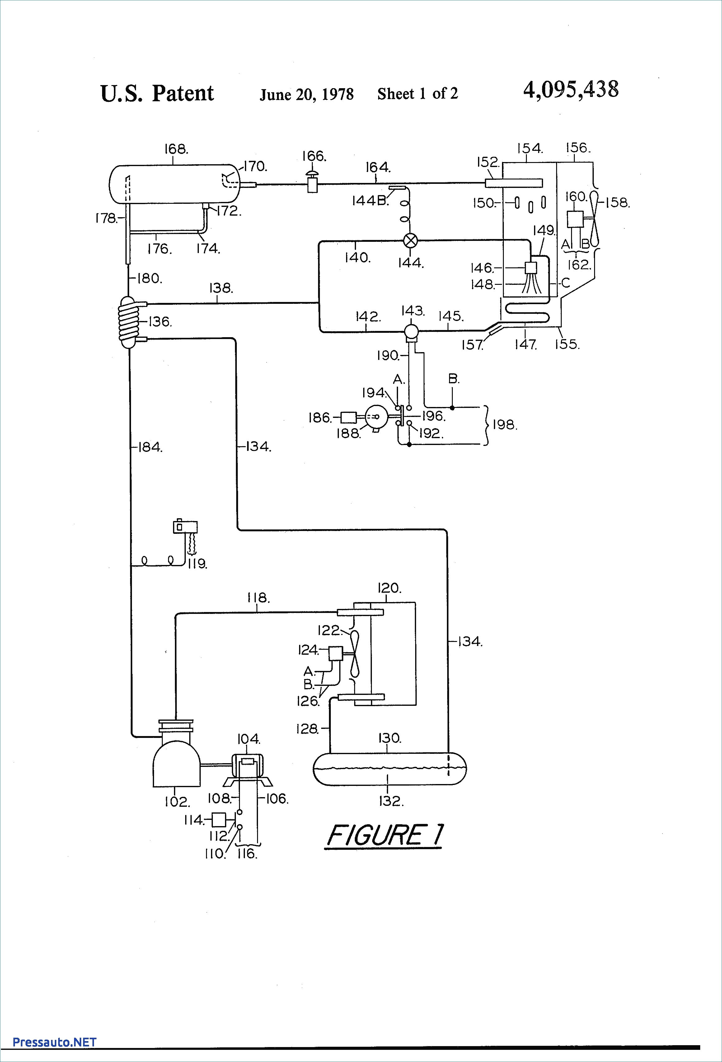
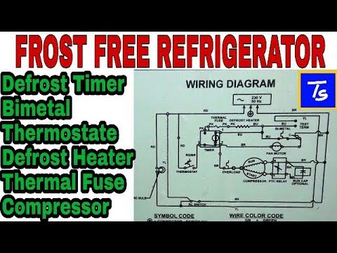
A schematic drawing of the timer is shown in figure 282. It reveals the elements of the circuit as streamlined shapes and also the power as well as signal links in between the tools.

Rheem Defrost Timer Wiring Diagrams E Defrost Control Ranco
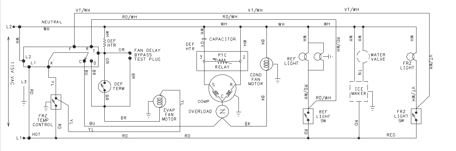
Defrost timer wiring diagram. A wiring diagram is a streamlined standard pictorial representation of an electrical circuit. October 18 2018 by larry a. Walk in freezer defrost timer wiring diagram. Variety of walk in freezer defrost timer wiring diagram. Paragon defrost timer 8145 20 wiring diagram gallery collection of paragon defrost timer 8145 20 wiring diagram. It shows the elements of the circuit as streamlined forms and also the power and also signal links in between the devices.
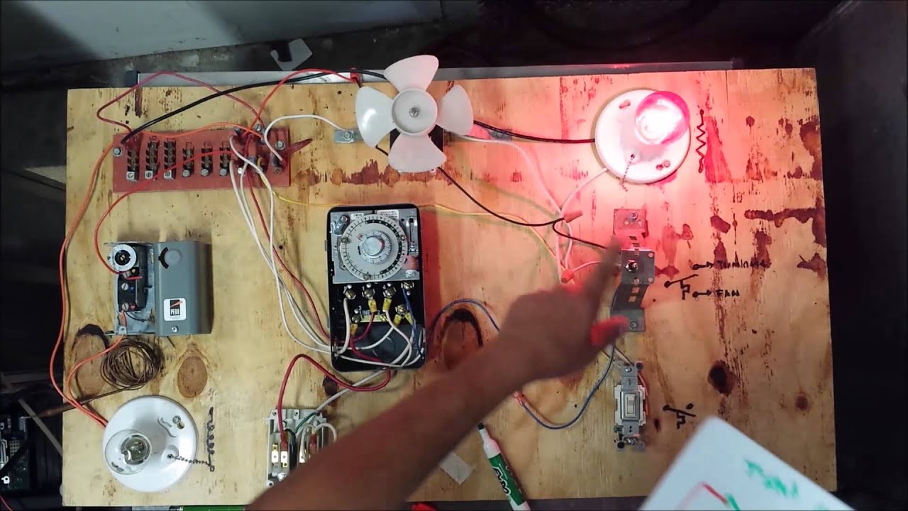
A wiring diagram is a streamlined standard pictorial depiction of an electrical circuit. Assortment of refrigerator defrost timer wiring diagram. The defrost timer is operated by a single phase synchronous motor like those used to operate electric wall clocks figure 281. It shows the components of the circuit as simplified forms and also the power as well as signal connections in between the gadgets. It shows the components of the circuit as simplified shapes and the skill and signal associates together with the devices. July 10 2018 by larry a.
A wiring diagram is a simplified traditional photographic depiction of an electrical circuit. Walk in freezer defrost timer wiring diagram wiring diagram is a simplified suitable pictorial representation of an electrical circuit. The contacts are operated by a cam that is gear driven by the clock motor.
Gallery of Defrost Timer Wiring Diagram