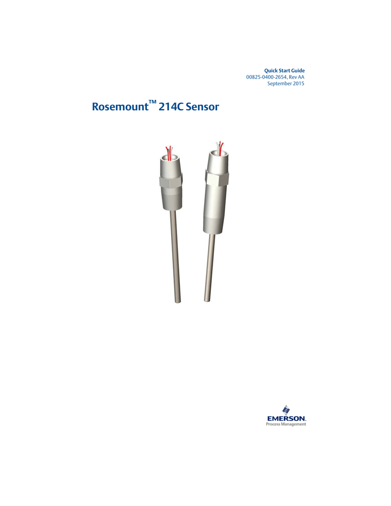
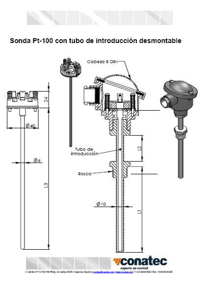
The rosemount 214c rtd temperature sensor is a pt 100 single or dual element resistant temperature detector rtd that covers a wide range of temperatures from 321 to 1112f 196 to 600c. Rosemount 214c accessories pdf manual download.

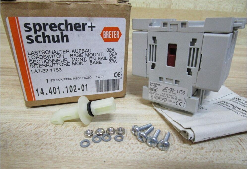
Hager Jae320开关断路器 工控栏目 机电之家网
Rosemount 214c wiring diagram. Rosemount 214c accessories pdf manual download. Rtd lead wire configuration per iec 60751 note to configure a single element 4 wire rtd as a 3 wire system connect only one white lead. The rosemount 214c has been examined and te sted to determine that the design meets the basic electrical mechanical and fire protection requirements by a nationally. Rtd lead wire configuration per iec 60751 note to configure a single element 4 wire rtd as a 3 wire system connect only one white lead. Page 3 quick start guide august 2017 10 wiring diagram for rtds figure 1. Emerson global emerson.
Rtd lead wire configuration per iec 60751 single element 3 wire single element 4 wire dual element 3 wire black black white white yellow white white note to configure a single element 4 wire rtd as a 3 wire system connect. An exceptional solution this sensor has a thin film and wire wound design for application flexibility. Product data sheet march 2019 00813 0500 2654 rev eb rosemount 214c temperature sensors primary product benefits high accuracy resistance temperature detectors rtd and various thermocouple types offered in a variety of element configurations calibration capabilities for increased measurement accuracy for rtds. Quick start guide 00825 0400 2654 rev ca february 2020 rosemount 214c sensor. 10 wiring diagram for rtds figure 1. The rosemount 214c has been examined and tested to determine that the design meets the basic electrical mechanical and fire protection requirements by a nationally.
Rtd lead wire configuration per iec 60751 single element 3 wire single element 4 wire dual element 3 wire black black white white yellow white white note to configure a single element 4 wire rtd as a 3 wire system. March 2019 quick start guide wiring diagram for rtds figure 1 1. 10 wiring diagram for rtds figure 1.


.jpg)


