The controls freak 95246 views. D automatic vent damper application the d automatic vent damper is a 24 vac motorized stack damper.
Sylk Enabled 0 2 10vdc Floating Actuator 88 Lb In
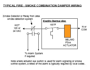
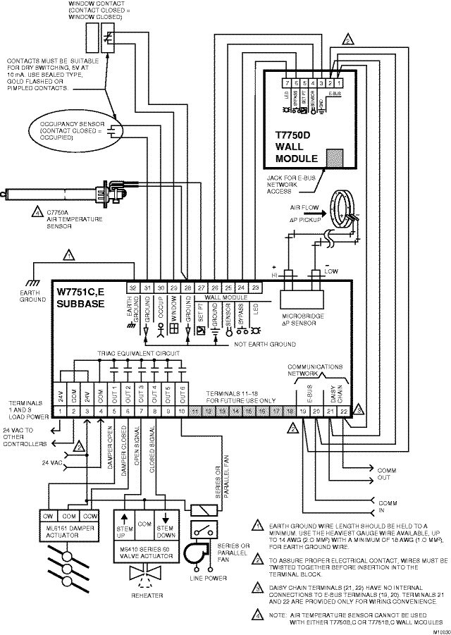
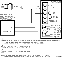
Damper actuator wiring diagram. Wiring diagram number quotation number. Energy sector water industry petro chemical industry and users from the most diverse industries worldwide rely on technologically sophisticated products by auma. Multiple actuators positioned by the same control signal may be powered from multiple transformers provided the following rules are followed. If the pop up blocker is turned on in your browser you are not able to view the wiring diagram. Use the d only on wiring diagram for d connection to. To change the spring return direction to cw mount the actuator to the damper shaft so that side b of the actuator is away from the damper.
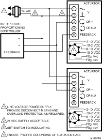
Selected wiring diagrams under documents attention. Please enter the address of our website in the address of web site to allow box. Sign up today to access the guides. Wire type and wire installation tips. 1 wires from all actuators are tied together and tied to the negative leg of the control signal. The wiring diagram opens in a pop up window.
Auma have been developing and building electric actuators and valve gearboxes for 50 years and is one of the leading manufacturers in the industry. Wiring rus s24 mod proportional actuators 3900 dr. Quick tip to make sure your belimo actuator seals your damper closed duration. Multiple actuators positioned by the same control signal may be powered from multiple transformers provided the following rules are followed. Learn how to access vehicle repair guides and diagrams through autozone rewards. Wire type and wire installation tips.
1 wires from all actuators are tied together and tied to the negative leg of the control signal. The damper closes off the furnace or boiler stack during the heating off cycle. 161 direct coupled actuators non spring return models n20 series mn6120 mn7220 and n34 series mn6134 mn7234 used for onoff control wiring for modulating control wiring for floating control wiring for auxiliary switches 2 3 4. Selecting the direction of rotation for ccw spring return direction mount the actuator to the damper shaft so that side a of the actuator is away from the damper. The transformers are properly sized. Actuator wiring diagrams direct coupled actuators non spring return models.
The transformers are properly sized.

