They help reduce costly downtime and protect sensitive electronic equipment against the damaging effects of transients caused by lightning utility switching internal load switching and more. They show the relative location of the components.

Installation Instructions For Eaton Spc Series Surge
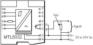
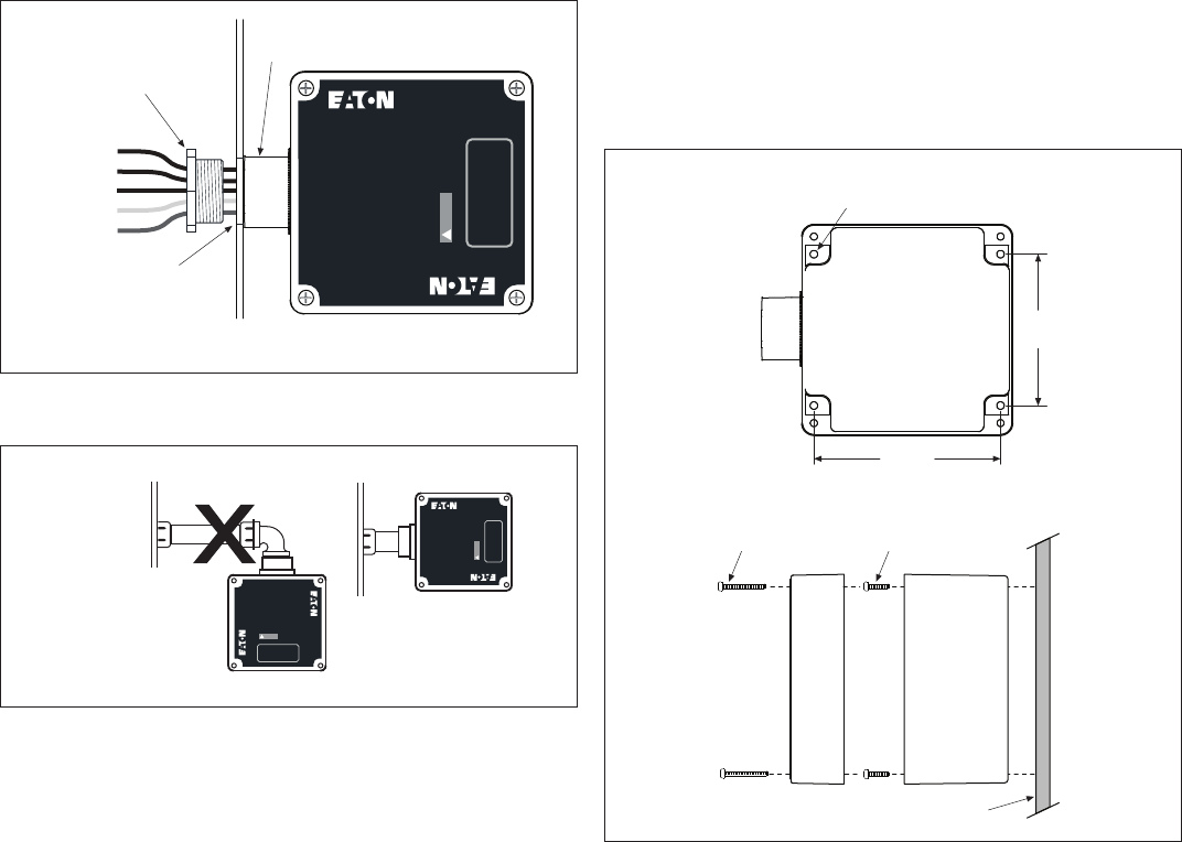
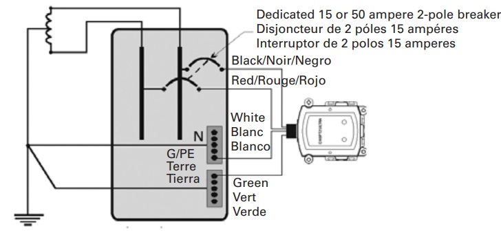
Eaton spd wiring diagram. See figures 6 7 8 and 9 on page 4. Eatons spc series is a configurable surge protective device providing safe robust downstream protection for critical equipment in commercial and light industrial applications. The eaton spd series should be mounted in such a way as to minimize any sharp bends in the wiring conduit. English us 1 jul 2014 470 kb. 23 installation procedures 1. The ideal mounting location for the eaton spd series is as close as possible to the electrical enclosure.
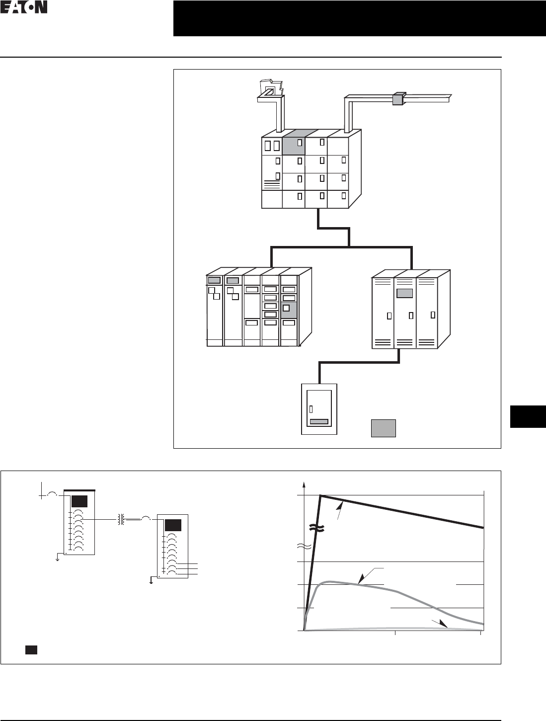
Locate the electrical systems applicable wiring diagram in section 23. They can be used as a guide when wiring the controller. Eaton surge protection devices pspd series eaton spd series instruction manual im01005032e. Featuring a compact nema 4x enclosure and eatons proprietary tri colored led indicator lights the spc offers configurable options including emirfi filtering audible alarm and form c contacts. Connect the spds neutral wire white to the systems neutral connection not required for. Figure 1 is a typical wiring diagram for a three phase mag.
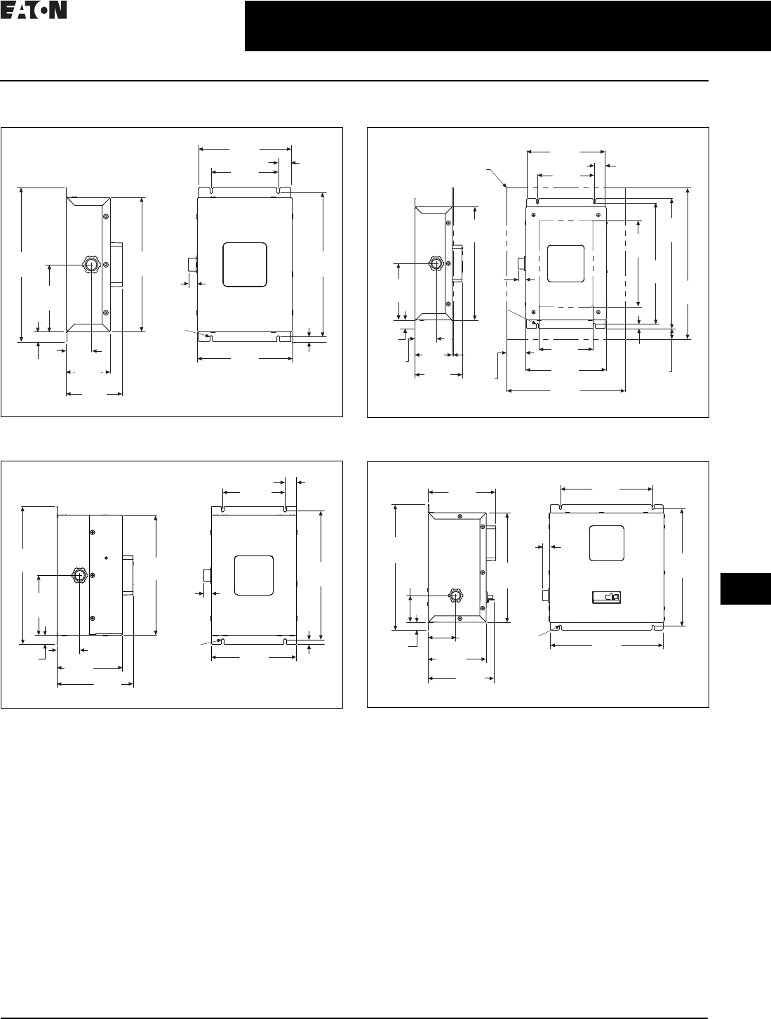
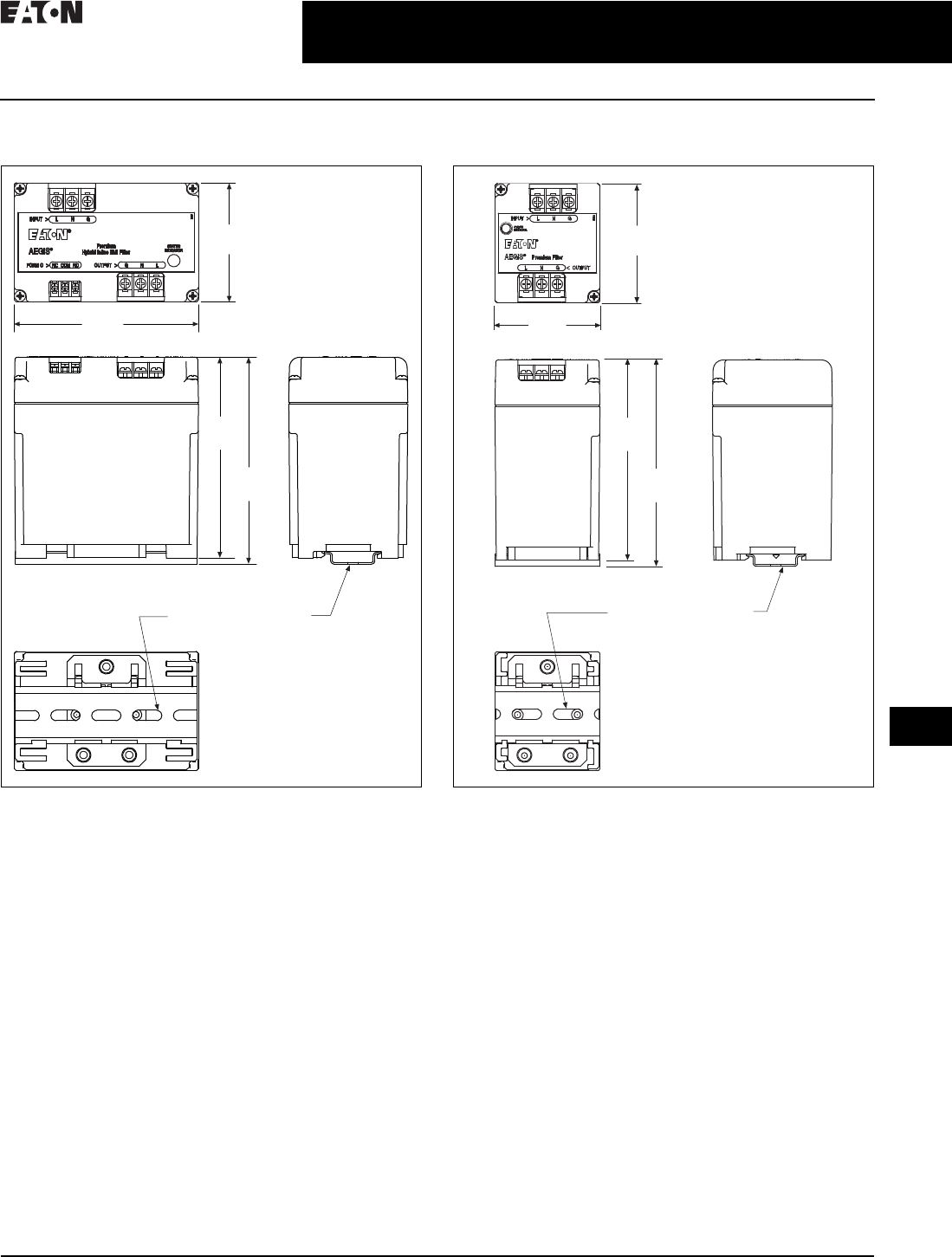
5 surge protective device for integrated units effective november 2013 figure 6. Eaton surge protection devices pspv series. Eaton has a comprehensive array of surge protective devices and suppressors to meet your needs ranging from residential to industrial applications. Dimensions for 50 200ka units mounting 880 2235. Eatons spd series can be installed next to above or below any existing electrical enclosure. You must refer to this diagram while wiring the spd.
You must refer to this diagram while wiring the spd. Page 6 eaton spd series instruction manual im01005019e rev. The eaton spd series should be mounted in such a way as to minimize any sharp bends in the wiring conduit. Reference this wiring diagram as necessary in steps 2 3 and 4. The ideal mounting location for the eaton spd series is as close as possible to the electrical enclosure. Bus connection figure 4.
Eaton top wiring kit for type s battery cabinet installation instructions. Wiring single phase units 230 l figure 8. Select the correct wiring diagram for the spd you are install ing. 23 installation procedures 1. Wiring diagrams sometimes called main or construc tion diagrams show the actual connection points for the wires to the components and terminals of the controller. Select the correct wiring diagram for the spd you are install ing.
Eatons spd series can be installed next to above or below any existing electrical enclosure. Connect the spds ground wire green to the systems ground connection.
Gallery of Eaton Spd Wiring Diagram