Rather several must be linked together to create a. Dali emergency lighting or mixture of dali and dali emergency lighting.

Systems Digital Illumination Interface Alliance
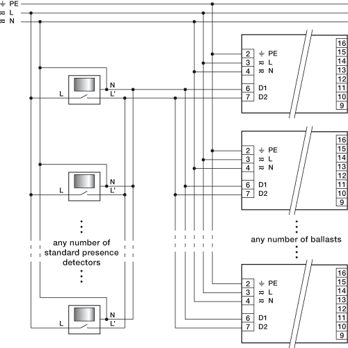
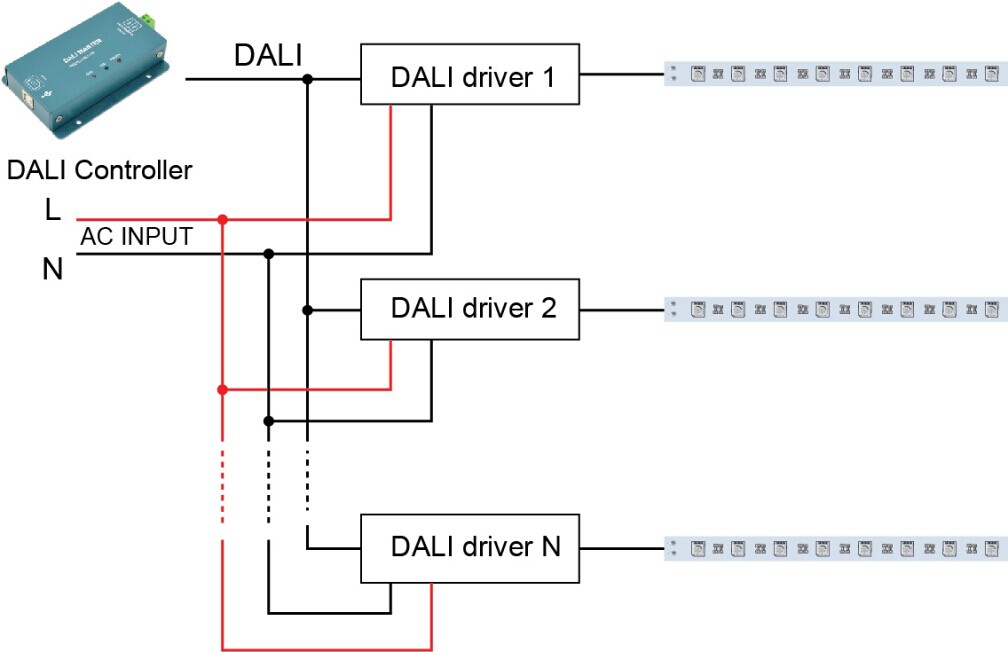
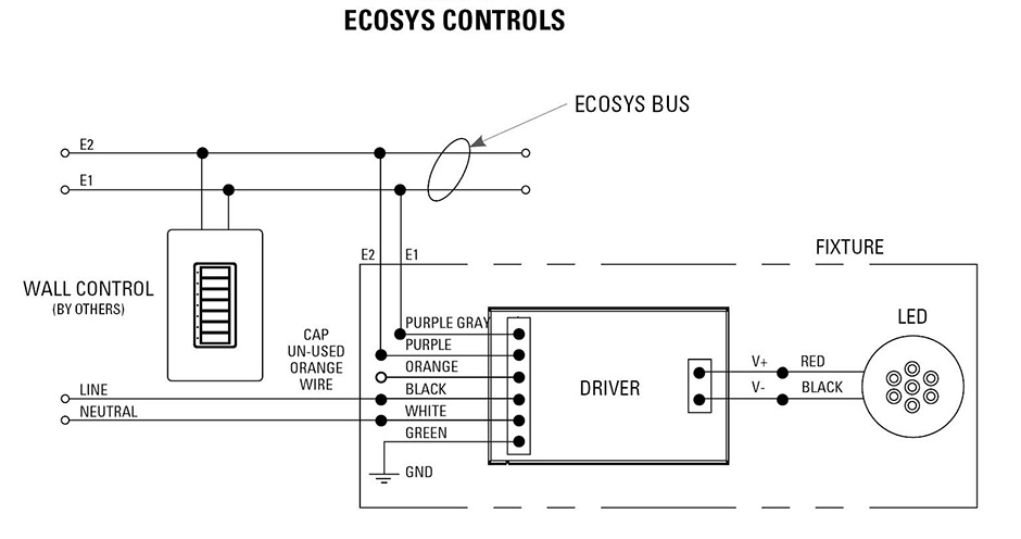
Dali lighting wiring diagram. Our eldoled dali dimming driver option dims down to 01 at minimum light level. One individual network isnt enough to cover an entire building. Dali communication is not polarity sensitive and a variety of connection configurations are possible with this protocol. A wiring diagram is a streamlined conventional pictorial representation of an electric circuit. A typical dali wiring diagram is shown below. The same setup can be used for dali lighting.
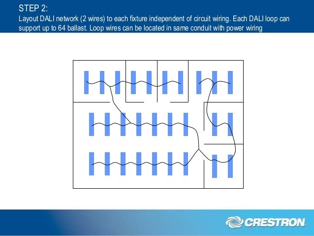
The line voltage and bus ba r are usually routed in the same cable found in the controller. Because all dali fittings are supplied with a switched active supply there is no added need for any extra circuit breakers or wiring. Typical dali layout fluorescent light emergency light downlight dali network boardroom showroom. Dali lighting control wiring diagram sample collection of dali lighting control wiring diagram. Usai lighting dali dimming solutions. Dali dali dali wiring consists of 2 control wires with a current limited power supply supplying a maximum current of 250ma.
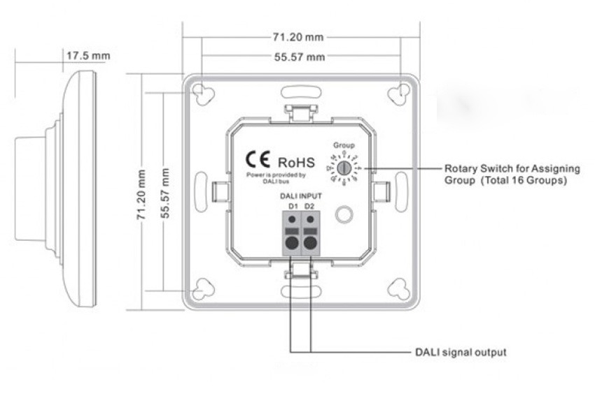
Due to the fact that the dali wires are not selv normal wiring rules apply and this allows. Put simply the lights are wired according to the australian electrical standards with an additional twin run to accommodate full dali control. A wiring diagram is a streamlined traditional pictorial depiction of an electrical circuit. It shows the components of the circuit as simplified shapes and also the power and also signal connections in between the gadgets. Dali wiring up to 64 dali lamps per network 16 groups within each network and 16 scenes per group diagram 2. Collection of dali lighting control wiring diagram download variety of dali lighting control wiring diagram.
Philips dynalite creates sophisticated reliable and energy efficient lighting control solutions for residential offices retail hospitality industry stadiums. It reveals the parts of the circuit as streamlined shapes and also the power as well as signal links between the devices. Led drivers and ballasts are connected using class 1 inside the conduit or class 2 outside the conduit wiring to make up a loop of no more than 64 led drivers or ballasts. Dali lighting wiring diagram. Refer to our dali concepts page for more information. It is available with a wide range of usai lighting.
The five wires mentioned make up 5 core cables which include neutral earth live or hot and two dali wires. To connect the dali wiring to the main light source you will need a ground wire a main wire a shielded wire and two wires from the controller. Each is given an address in the dali system and the loop is connected to a dali control device.
