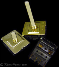
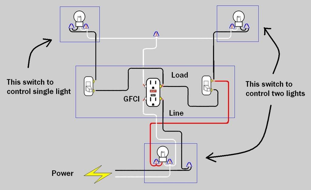
As you can see in the schematic diagram of 2 way switch circuit below the common of both the switches are short circuited. Notice on the wiring diagram that of the 10 prongs spade connectors called termianls on the back four 4 make the rocker switch lights function while the remaining six are used for the electromechanical switching contacts.

Wrg 5568 Mariner Throttle Control Wiring Diagram
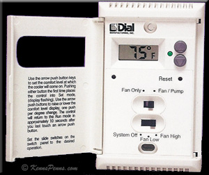
Rsk 2 switch wiring diagram. Pin1 of both the switches are connected with the phase or live wire and pin2 of both the switches are connected with the one end of the lamp. With wbl or mbl brackets only lti series switches shown with nylon brackets nbl wbl mbl only for other brackets or additonal circuits consult factory standard switch wiring diagrams carling technologies inc. With independent lamp circuit only 3. Codes for correct installation of evaporative cooler switch and wall switch box correct wiring procedures and effective grounding. By wiring a 2 way switch the circuit below shows the basic concept of electricity flow to the load. Mpn the above is a basic wiring schematic for a swamp cooler switch.
Route a 12 gauge 120 volt hot wire usually color coded black or red to the location of the switch there is typically no need for a ground or neutral wire to the switch. Lasco evaporative water cooler thermostat with two speed six. 2 speed 2 gang rsk 2 metal wall switch for evaporative coolers. The other end of the lamp is connected with neutral line of ac power supply. Switch w hite ground no connection red black wiring diagram for using a rs2 rocker switch and a rac stick grip or ros 4 4 way switch 1 amp fuse stick grips wired according to style 2 in grip wiring instructions. This switch body does have two isolated negative inputs t9 and t7 for each lamp or led in the switch.
This is a completed circuit. Catalog page vol 21. This diagram is a basic schematic and is not intended to represent all. 611 621 610 620 ta tila 2fa. Evaporative swamp cooler switch thermostat wiring. With lighting sequences 10 20 30 4050 only 4.
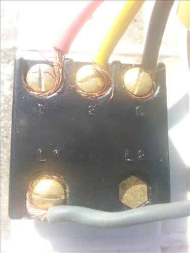
The reverse of the switch will have four terminals typically marked l1 1 2 and c connect the 120 volt hot wire to the terminal marked l1. 0810 what you are doing with this method of wiring is making the rs2 rocker switch perform like two single pole single throw spst. Mounting screws and wiring diagram. Motor and pump voltage and amperage must not exceed switch specifications. This switch is recommended for 120 volt applications only. Lets assume the load you are controlling is a light.
The electricity flows from the hot wire black through the 2 way switch shown in off position and then to the light and returns through the neutral wire white.
Gallery of Rsk 2 Switch Wiring Diagram