How to wire an exit button or sensor description. Video intercom digital vts1500a 20 users manual 100 vts1500a.

Dahua Dhi Vto1210c X Order Now Webstore4
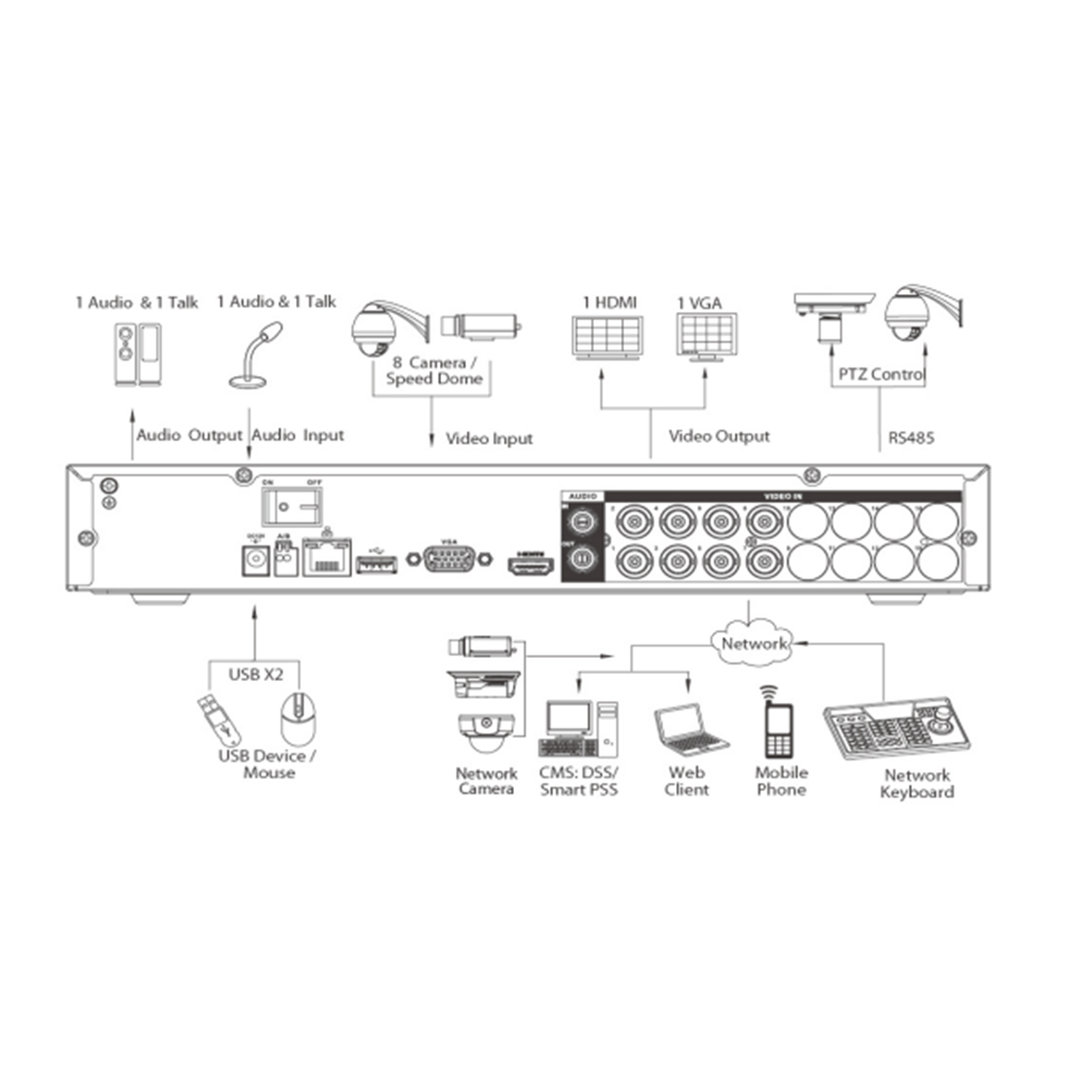
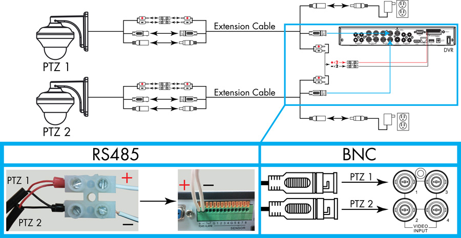
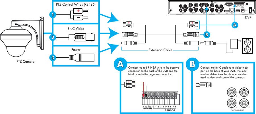
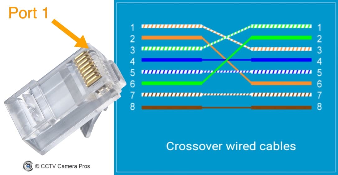
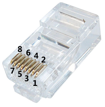
Dahua wiring diagram. Dahua pinout wiring diagram apart from the example shown above many of the dahua ip cameras can have a different pinout diagram. Electric control lock and electromagnetic lock power supply connect to lock door sensor and user port unlock button. 868625mm 30c60c led light stainless steel 912825mm dc12v 30c 60c infrared induction stainless steel 868625mm dc12v 30c 60c plastic 868650mm 30c 60c mifare card 1356mhz from philip. Dahua camera ip poe pinout diagram wesprzyj mnie. Dahua logo key fob id white card id key fob model asf900 asf905 asf908 asf921 ic s50 ic sm yx 4cm id em id sm description abs plastic. Rj45 network port crystal head.
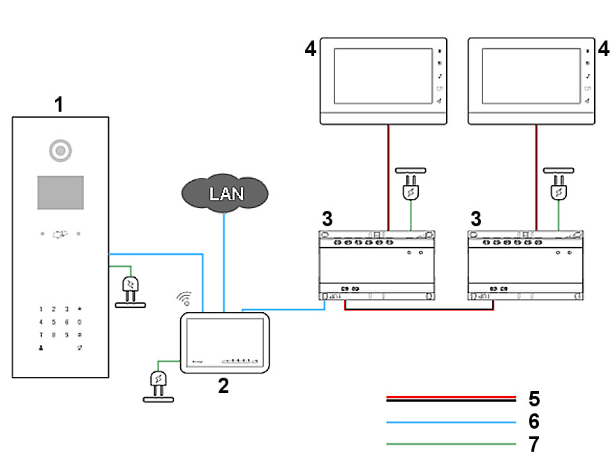
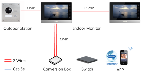
Dhi vto2202f p ip outdoor station dhi vth2421fw p indoor monitor dh pfs3005 4et 60 poe switch vtm115 surface mount box for dhi vto2202f p one key config. Wiring figure 2 7 23 wiring see figure 2 8. How to re wire a broken dahua ip camera cable cat5e rj45. Dahua housing dahua model outdoor station indoor station short description specifications vto firmware vto voice firmware vth firmware dhi ktp01s dhi vto2202f p. Analog wiring diagram 100 villa and apartment system click here to download. 1 how to add a magnetic lock to a vto2111d wp.
After wiring please test using the door unlock function or wire in a push button for testing. From dahua wiki video intercom. Four door access controller support 100000 valid cards 300000 records. This wiring diagram is to describe where to wire door exit button sensor to dahua access controller. Video intercom ip wiring diagram 100 villa and apartment system click here to download. Make the connection as shown on the illustration.
Models image type description specification quick start guide manual firmware dhi asc1204b. Now wire your door controlled using the diagram below. Video intercom access control extension module dee1010b users manual 100 dee1010b click here to download. Take a look at the picture below on the left side its the rj45 pinout t 568b and the right side the dahua ip camera poe pinout color coded wiring diagram. Figure 2 8 component note name via convertor connect to network cable.
Gallery of Dahua Wiring Diagram