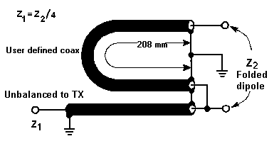
To the outside antenna ground wire not included lightning. The driven element of a yagi is the feed point where the feed line is attached from the transmitter to the yagi to perform the transfer of power from the transmitter to the antenna.

Epits Running A Test Flight
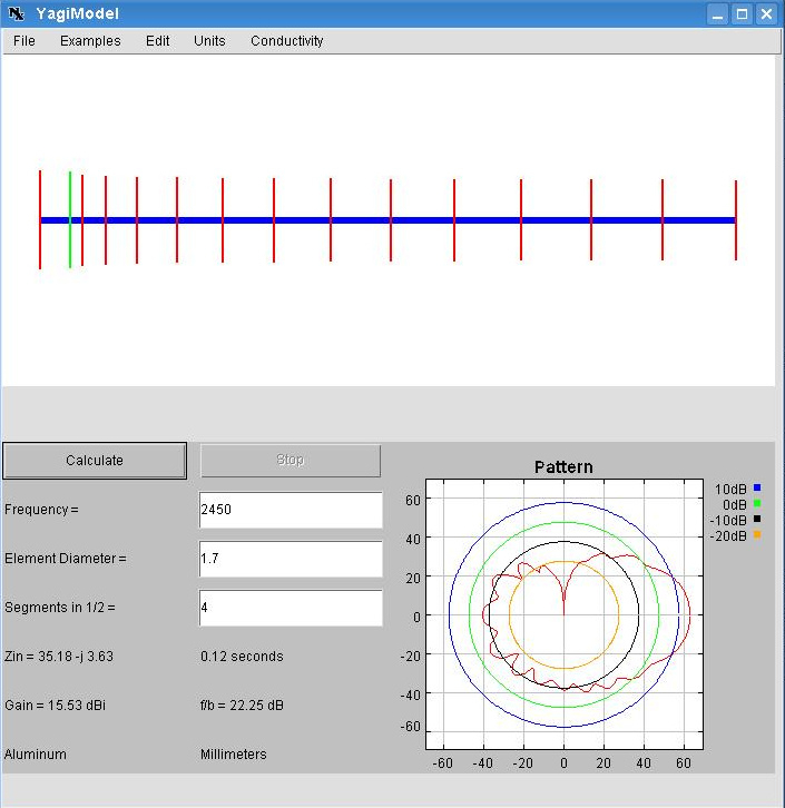
Yagi antenna wiring diagram. Yagi antenna design formula. Wide band directional antenna 700 mhz 2700 mhz 304411. However you could mount on other poles outdoor if it is available. The antenna gain is a function of the number of dipole elements. I used a yagi modeler java applet to generate the diagram. Trim approximately 15 inches of the outer jacket of the control cable 4 or 6 wire depending on which ehu.
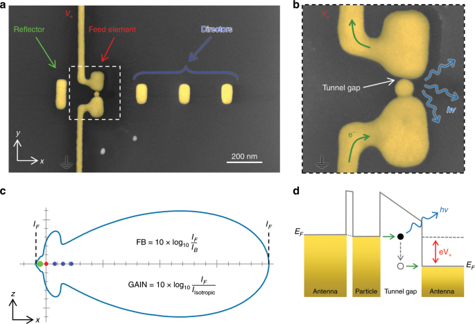
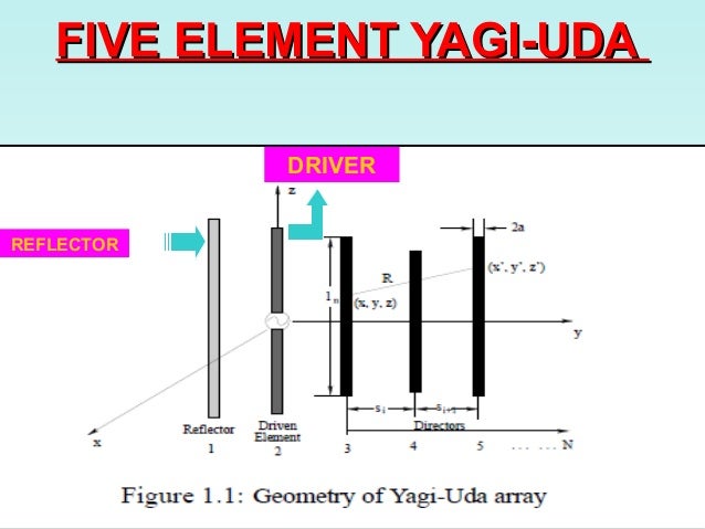
Print out the scaled yagi antenna template download from next step. Yagi antenna 301111 2. The parasitic elements of the yagi antenna operate by re radiating their signals in a slightly different phase to that of the. A yagiuda antenna commonly known as a yagi antenna is a directional antenna consisting of multiple parallel elements in a line usually half wave dipoles made of metal rods. Yagi uda antenna showing element types yagi antenna theory the basics. Gt 166 n where n is the number of elements in the yagi antenna.
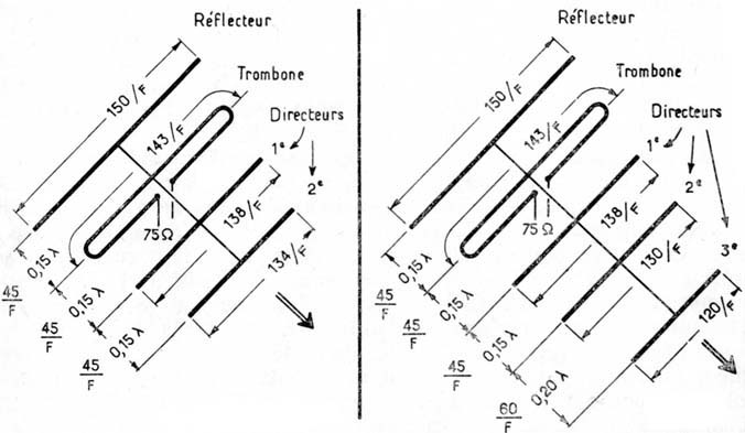
A dipole driven element will be resonant when its electrical length is 12 of the wavelength of the frequency applied to its feed point. Yagi antenna to improve signal transmission or reception in specific directions basic elements either vertical or horizontal can be combined to form arrays. For yagi antenna and panel type outdoor antenna the best place to mount is on the pole that mount the tv antenna as it is usually the highest location available in a house and so the signal reception will be better. Outdoor antenna options indoor antenna options accessories 1. Use popsicle sticks to build the antennas backbone and hold it together. Yagiuda antennas consist of a single driven element connected to the transmitter or receiver with a transmission line and additional parasitic elements which are not connected to the transmitter or receiver.
Remove the shield material the support thread and cut the ground wire off as shown in figure 11. The inside antenna may be mounted on the wall directly under the outside antenna in the null zone. Trim paper clips to size and glue them to the template. Follow the directions below for wiring each of your element housing units ehu to the connector junction box. One of the major keys to understanding yagi theory is a knowledge of the phases of the currents flowing in the different elements of the antenna. The most common form is the yagi uda parasitic array commonly referred to as a yagi array or beam.
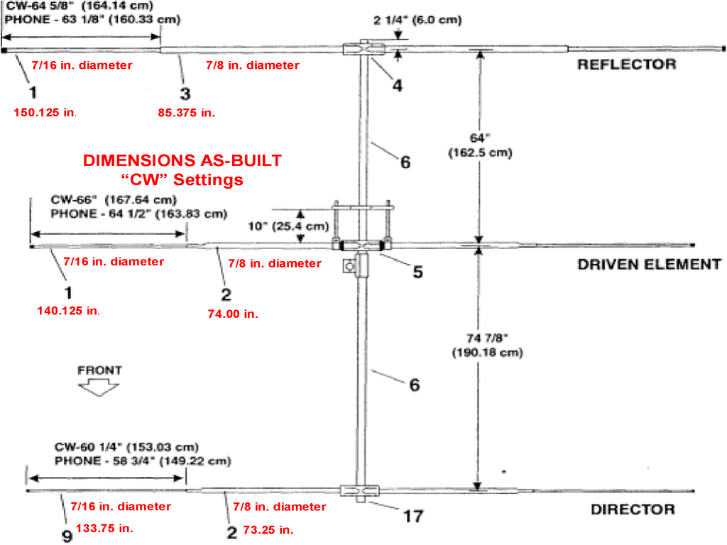
The dipole in the array is driven and another element 5 longer operates as a reflector. Connect the usb device to the antenna. This arrangement gives the antenna directionality that a single dipole lacks.
Gallery of Yagi Antenna Wiring Diagram