Connecting to existing wiring or chassis ground other than the. Signs that stand for the elements in the circuit and lines that stand for the connections between them.

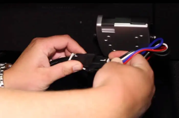
Trailer Brake Controller Installation How To 5 Easy Steps
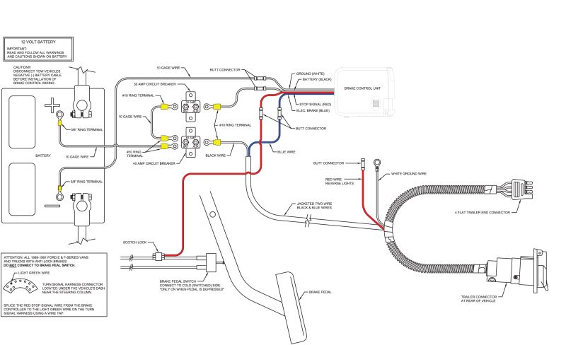
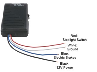
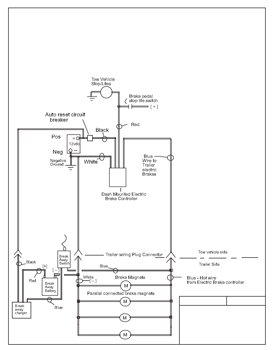
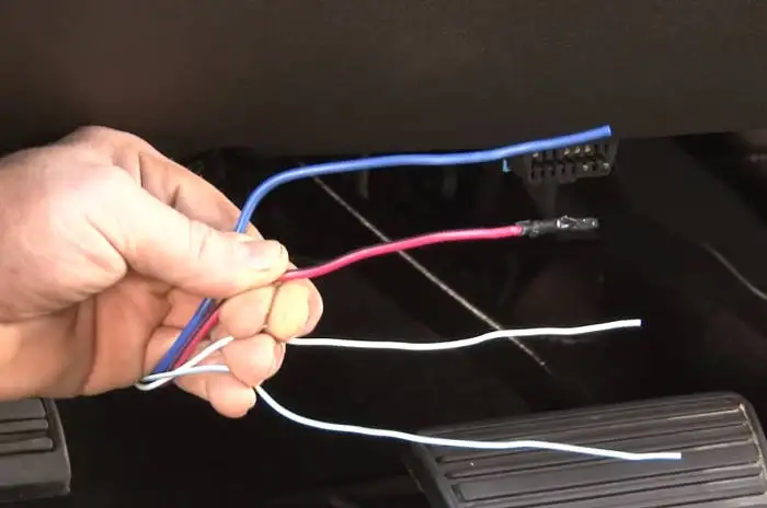
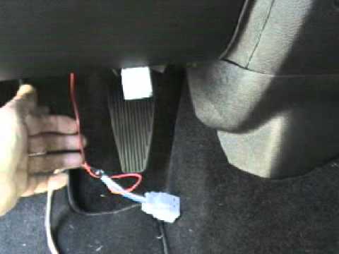
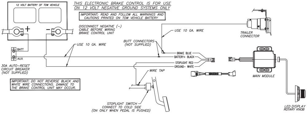
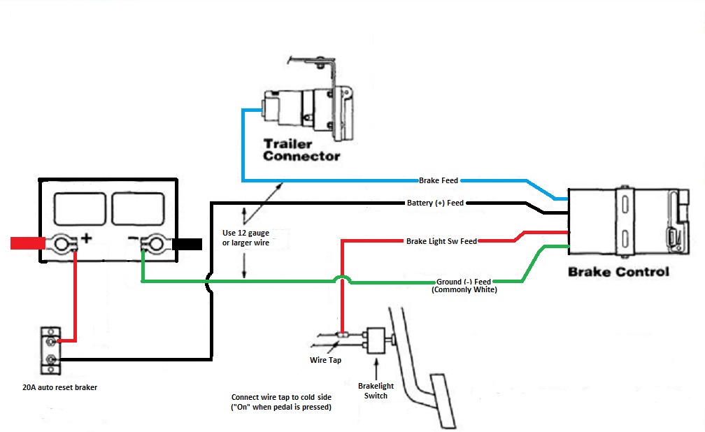
Curt brake controller wiring diagram. If your vehicle is not equipped with a plug and play harness you can also splice in wiring for connecting a brake controller. Variety of curt discovery brake controller wiring diagram. When passing wires through sheet metal always insert two 10 gauge wires one white and one black from the mounted brake control to the battery area. Curt brake controller wiring diagram whats wiring diagram. It reveals the components of the circuit as simplified shapes and the power as well as signal connections in between the devices. A wiring diagram is a kind of schematic which uses abstract photographic signs to reveal all the affiliations of elements in a system.
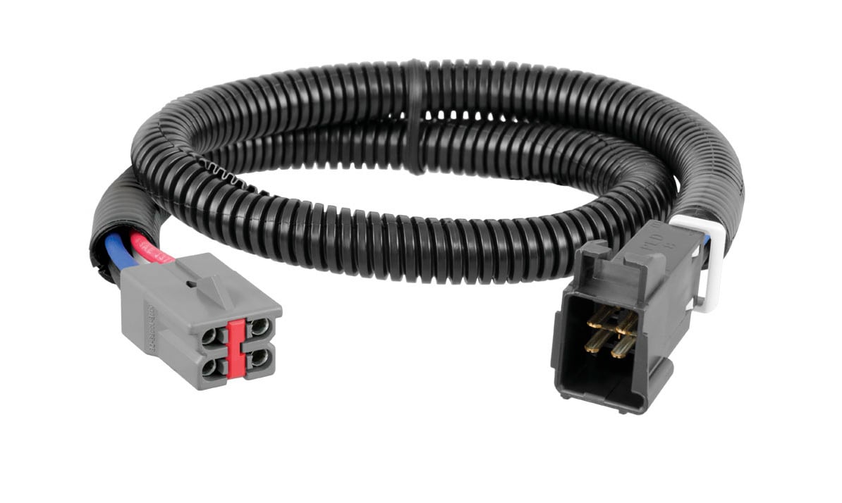
Wiring layouts are made up of 2 things. Using a ring terminal connect the black. Installing a brake controller involves disconnecting the vehicle battery mounting the brake controller onto dash and plugging the unit in with a vehicle specific wiring harness. Make sure that both positive and ground connections are made directly to the tow vehicles battery. A wiring diagram is a streamlined conventional photographic depiction of an electric circuit. With a factory brake control plug we suggest purchasing the curt universal brake control wiring kit 51500.
It shows the elements of the circuit as simplified shapes and the power as well as signal connections between the gadgets. We suggest the curt brake control wiring kit part 51500. A wiring diagram is a streamlined standard pictorial representation of an electrical circuit. As close to the battery as possible. In this guide we cover step by step how to install a brake controller. Page 10 wiring diagram important.
Collection of curt brake controller wiring diagram.
Gallery of Curt Brake Controller Wiring Diagram