Power goes to l2 black and l3 white 3. This wire is already connected from the factory.
Pdf Instead Tpi Corporation
Contactor tmc 18 wiring diagram. Motor goes to t2 black and t3white 2. Operating switch os terminal 3 goes to l3 with the power connection 4. Ls gmc 18 3 pole 18 amp contactor with a 240vac coil. Wiring diagram book a1 15 b1 b2 16 18 b3 a2 b1 b3 15 supply voltage 16 18 l m h 2 levels b2 l1 f u 1 460 v f u 2 l2 l3 gnd h1 h3 h2 h4 f u 3 x1a f u 4 f u 5 x2a r power on optional x1 x2115 v 230 v h1 h3 h2 h4 optional connection. Posted january 18 by springercontrols the below wiring diagram shows how we would assemble a complete motor starter with a startstop button for a single phase motor. Operating switch os terminal 4 goes to relay terminal rt a2 5.
Operating switch os terminal 4 goes to relay terminal rt a2 5. 240 volts ac and 480 volts ac are commonly used for these large pieces of. Description covering four rating classes in single size. Connect the two motor wires to terminals on the ac contactor marked t2 t3. These wires are already connected from the factory. Tmc 18 contactor 220v single phase 60hz 3hp factory installed step 7 installing safety interrupt switch 1.
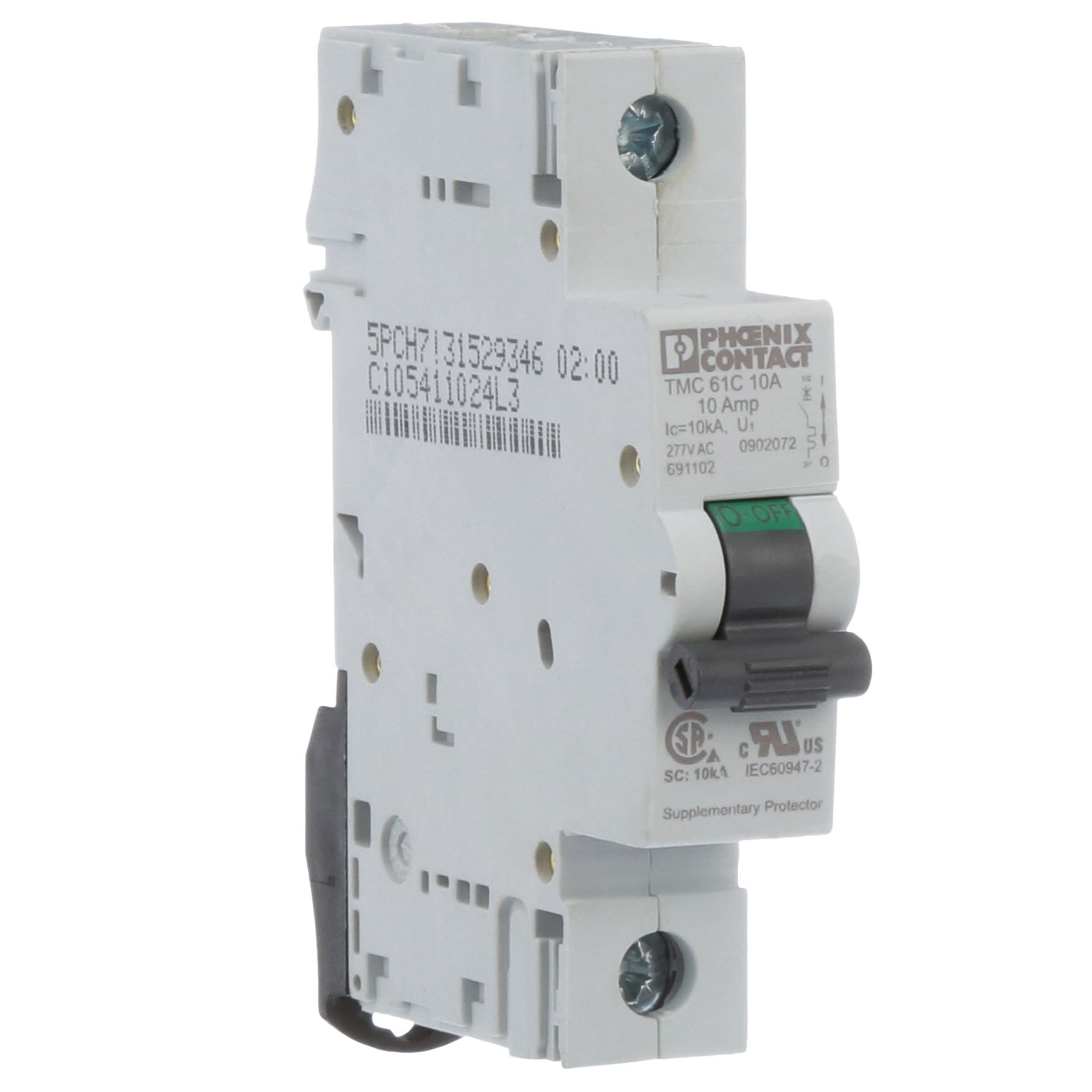
44 mm wide 1no1nc auxiliary contacts built in as standard. Tmc 18 contactor 220v single phase 60hz 3hp factory installed step 7 installing safety interrupt switch 1. How to wire a contactor. What is a contactor. Remove the entire wire that connects from the up button to a1 on the ac contactor. These lines far exceed the 120 volts ac standard in most homes.
How does a contactor work. It reveals the elements of the circuit as streamlined forms and the power and also signal links between the gadgets. Many large pieces of equipment are powered directly from high voltage lines. The above diagram is a complete method of single phase motor wiring with circuit breaker and contactor. Operating switch os terminal 3 goes to l3 with the power connection 4. Collection of ac contactor wiring diagram.
Connect the short wire a2 to l3 on the ac contactor. Click here to see a pdf spec file on this lg gmc contactor. A wiring diagram is a simplified traditional pictorial representation of an electrical circuit. In the above one phase motor wiring i first connect a 2 pole circuit breaker and after that i connect the supply to motor starter and then i do cont actor coil wiring with normally close push button switch and normally open push button switch and in last i do connection between capacitor. Contactor tmc 18 wiring diagram wiring a single phase motor through a 3 phase contactor. Motor goes to t2 black and t3white 2.
3 pole main contact finger proof design din rail or screw mountable small physical size. Iec contactors 41 42 iec contactors and auxiliary contact blocks 41. Power goes to l2 black and l3 white 3.
Gallery of Contactor Tmc 18 Wiring Diagram