Butterfly valves should be installed a minimum of six 6 pipe diameters from other line components. Wellborn assortment of butterfly valve wiring diagram.

Butterball Wiring Diagram Manualzz
Butterfly valve wiring diagram. Butterfly valve diagram với chất liệu inox 201 inox 304 inox 304l inox 316 inox 316l với tiêu chuẩn din sms 3a bs din ansi asme iso idf và. Because of the unique seat design nibco butterfly valves do not require the use of flange gaskets. Single leads soldered to switch tabs installation must comply with nfpa 13 and nfpa 72. This is not always practical. Dual leads soldered to switch tabs switch 2. Tm 1050 resilient seated butterfly valves technical manual series 20 series 21 series 30 series 31 series 22 series 23 series 32 series 33 series 35 series 36 series 31h series 3a series 3ah series 31u series 35f series 36h.
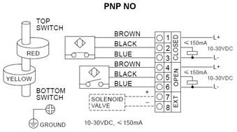
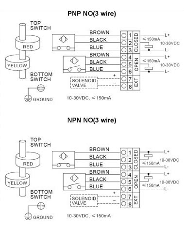
Butterfly valves are provided with two sets of factory installed inter nal switches each having spdt con tacts ref. Dultmeier sales will be closed thursday november 22nd and friday november 23rd in observance of thanksgiving. Nibco butterfly valves are bi directional and may be installed with flow in either direction. Butterfly valve switch installation 13 installation when the valves are received from the manufacture they should be handled carefully to avoid breakage and damage to the seating area. A wiring diagram is a kind of schematic which utilizes abstract pictorial icons to reveal all the interconnections of components in a system. When the valve closes hard it is usually due to debris lodged in the sealing area.
A wiring diagram is a streamlined conventional photographic representation of an electric circuit. Butterfly valve wiring diagram exactly whats wiring diagram. Care should be taken when installing a butterfly valve adjacent to lined pipe as cast fittings or schedule 80 plastic pipe. Tfp1517 page 5 of 6. Also view our online catalog for all our keystone valves products. In some cases the disc in the opened position will interfere with the adjacent component.
Trimfit butterfly valves wiring diagram switch shown in position with valve fully open switch 1. Cap unused leads with wire nuts and tuck into a junction box not provided. Before installation of the valve clean piping flange and coupling. Lug and wafer style valves are designed and suitable for installation between ansi class 125 and 150 flanges. September 4 2018 july 7 2018 by larry a. Keystone valves parts diagrams from dultmeier sales.
It reveals the components of the circuit as streamlined shapes as well as the power and signal connections in between the gadgets. Model bfv 250 butterfly valve internal switch wiring diagram with valve in open position graph a model bfv 250 wafer style butterfly valve nominal pressure drop versus flow.
Gallery of Butterfly Valve Wiring Diagram