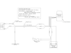
Rea aay sitc layard trailer lu ro to veicle cotroller typically lue 1 olt 0 ap circuit ro to eicle roud ro to eicle reaaway attery 1 olt ap hour iiu lue lack hite. Installer per the wiring diagram.

Titan Brake Rite Optional Australian 12 Pin Flat Harness 4862800
Brakerite wiring diagram. With the brakerite ii either the sd or rf control module is used both systems described below. Approximate physical envelope for power unit is 6 front to back 7 14. 515 265 9212 48158 10 2015 rev. Weather pack connectors are connected in line to the existing brakerite harness near the actuator. When making connections to the trailers wiring harness the desired. Figure 2 brakerite ii sd wiring diagram installation mounting location of any brakerite model is at discretion of installer however accessibility for service protection from damage and ability to minimize length while protecting brake lines are factors to be considered.
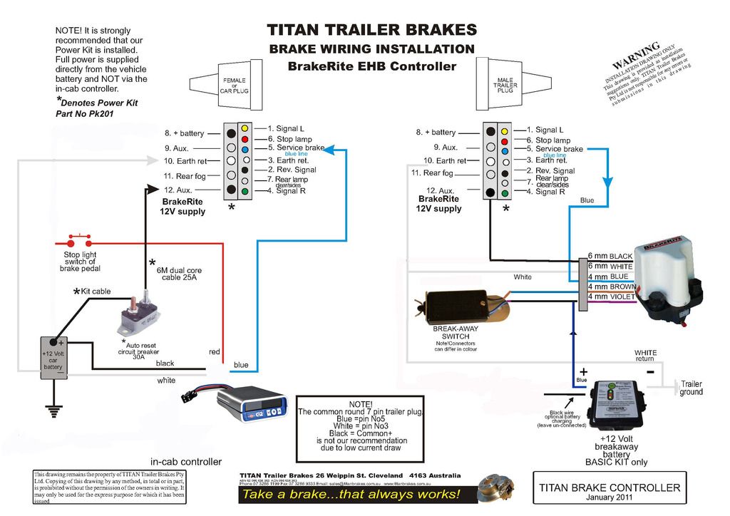
This particular actuator is designed for use with hydraulic drum brakes and features 1000 psi of hydraulic pressure. I have attached the wiring diagram for the titan brakerite ehb electric hydraulic actuator t4822500 that you referenced. 800 usa bear or 800 872 2327 fax. The brakerite ii has no ecb and has a three wire cable with a female weather pack plug therefore it requires a control module. Brakerite wires and wire connections the wires on the brakerite system wiring harness are approximately 2 metres long see page 9 to allow for flexibility when mounting the unit however extensions may be required to connect unit to the trailers electrical wiring. K58 036 01 wiring diagram for brakerite plug and play actuators.
Figure 1 brakerite ehb wiring diagram figure 2 brakerite ii sd wiring diagram. If not properly connected the unit will not perform properly or at all. Page 7 of 16 a titan company 2345 east market street des moines ia 50317 phone.


