The second part involves the control circuits. An automotive alternator can be converted into a powerful hybrid brushless motor and can exceed the performance of conventional brushless motors bldc.

Sl 0775 Mercruiser 260 V8 Alternator Wire Diagram Help
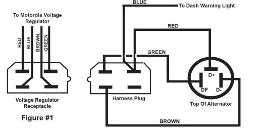
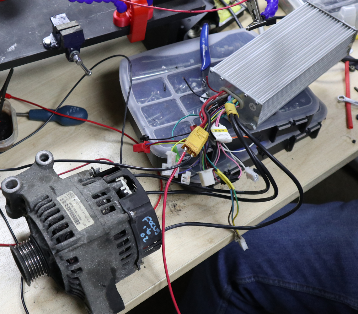
Alternator to motor wiring diagram. The early gm alternator is the 10dn series alternator and was used on gm vehicles from about 1963 1970. Collection of denso alternator wiring schematic. It is a diagram for the alternator in a ford focus see also ford focus repair manual ford escort ford f 100 ford taurus ford mustang ford model t ford gt40 ford thunderbird ford shelby cobra and other ford cars that use the similar alternator. And that is all. Some better esc have switch for changing direction but you can do manually switching two phase. If not the structure will not function as it ought to be.
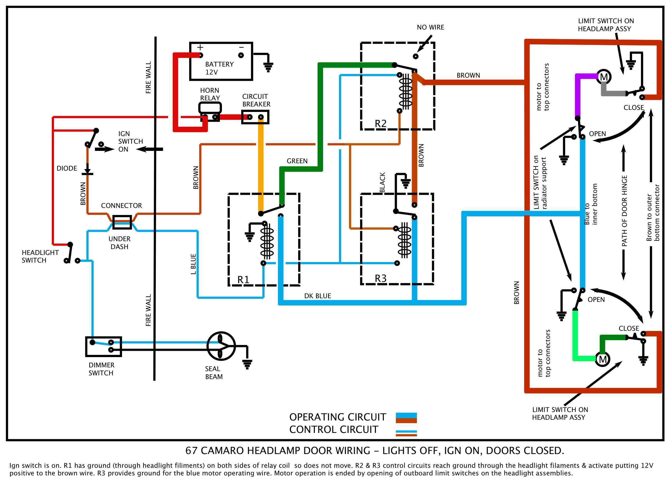
Classic industries offers a wide selection of 1971 chevrolet camaro parts including 1971 chevrolet camaro interior parts and soft trim 1971 chevrolet camaro exterior sheet metal 1971 chevrolet camaro moldings 1971 chevrolet camaro emblems 1971 chevrolet camaro weatherstrip and unique. Please be careful this is a powerful motor and it can hurt you. Each part ought to be placed and linked to other parts in particular way. Ford alternator wiring diagram this is the diagram of every components in the alternator. After wiring assemble everything back except diodes. It reveals the elements of the circuit as simplified forms and the power and also signal connections in between the tools.
The first part deals with the power circuit connections because starters consume and alternators produce great amounts of power. Starters are turned on and off and alternator output is. If you are able to look at a manufacturers diagram of the alternators connectors the wire that slides over pin 1 of the alternator leads to the positive connection on the vehicles battery and senses voltage. If the voltage rises above or falls below 12 volts the alternators internal voltage increases or reduces power output to. Alternator exciter wiring diagram alternator exciter circuit diagram alternator exciter wiring diagram every electrical arrangement is made up of various different pieces. The process for wiring a starter and an alternator on a car is divided into two parts.
A car alternator changed over to a brushless hybrid motor can put out in excess of 10 hp. The alternator charge wire routes direct to the battery and not through any switch connection the alternator will not operate correctly if not connected direct to battery or directly through the ammeter. And one more think. You can also use 12v on rotor but motor will bi slow and spent 3 amps on rotor. The wiring that comes with our kits should be used as it is sized to handle the amperage. Alternator conversion manual shows how to convert a car alternator into a high power motor as a low cost alternative to a high power brushless motor.
A wiring diagram is a simplified traditional pictorial depiction of an electrical circuit.
Gallery of Alternator To Motor Wiring Diagram