It is used to improve power factor to meet the current requirement to reduce the billing and also to improve feeder voltage regulation. Why we use apfc panel.

Wrg 7045 Ats Diagram 3 Wire Pump Pressure Control
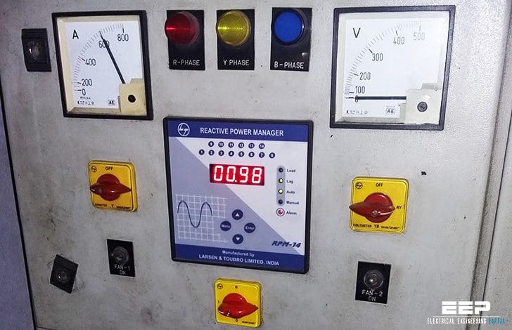
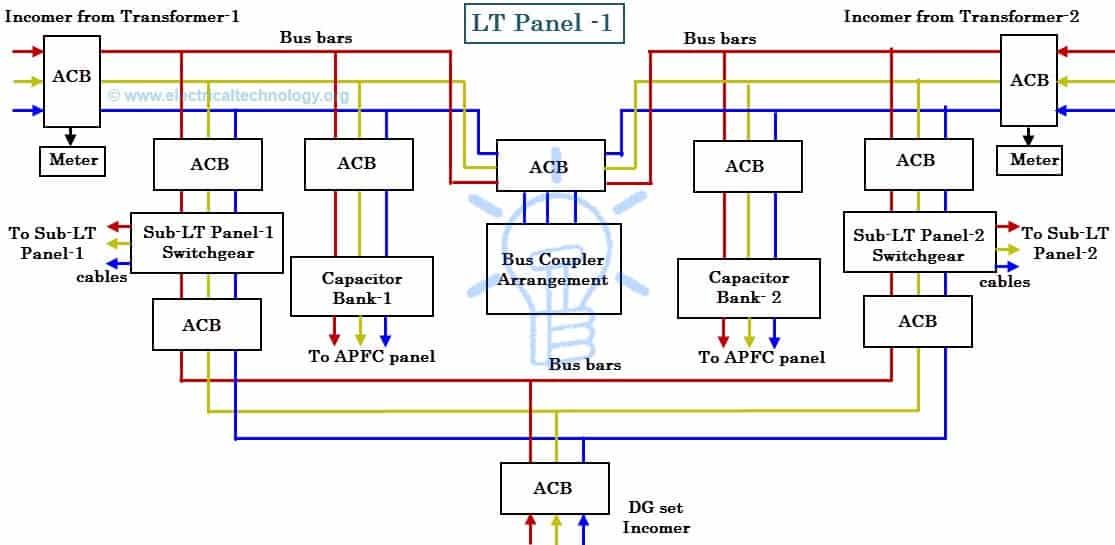
Apfc panel control wiring diagram. कपसटर क कस चक करत ह how to check capacitors. Why we need power factor control and how to maintain power factor and how automatic power factor relay is working and how to do wiring for apfc panel also explained in this video so watch the. Apfc or automatic factor control panel panels are widely used for power factor optimization. Through the thousands of pictures on the web about relay panel wiring diagram we choices the top libraries using best quality simply for you all and now this images is actually one of images choices in your best photos gallery regarding relay panel wiring diagrami really hope you may want it. Pfcs measure voltage and current calculates the reactive and active power and switches capacitors depending on the reactive power that needs to be corrected. Apfc panel control wiring diagram how to do control wiring of auto power factor correction panel electrical infinity.
Days one apfc panel cannot be used for different application. All wiring inside the control panel is carried out with 1000600 v grade fr lsh. Control wiring diagram. Apfc stands for auto power factor correction panel. Safe sure 64 lt switchgear e s p s e r v i c e m a n u a l. That photograph apfc relay control wiring diagram apfc panel wiring diagram pdf within relay panel.
15 apfc panel for automatic control of pf pfc. Billing can be reduced almost to 40. In order to improve power factor so that billing is reduced by avoid penalty from governments through introducing kvars into power. Make apfc of your own. Basic theory of. Control panel is complete with all internal wiring and ready for purchasers external cable connections at the outgoing terminals.
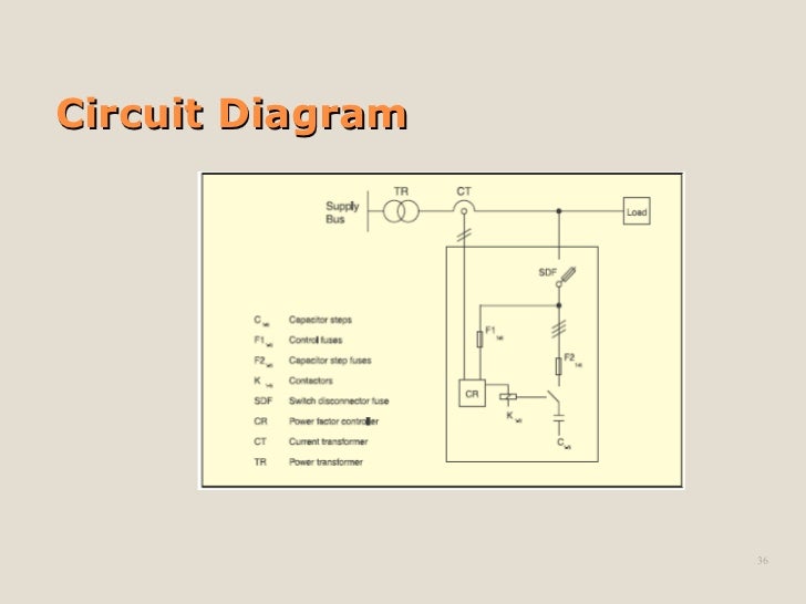
All inter modular wiring within the control panel for control and interlock looping is carried out by the control panel supplier. Apfc panel f2 h1 f1 1 m c 1 m k 1 m sdf cr t tr power transformer u rent a sfo m p ow erfa c tn l switch disconnector fuse contactors capacitor stop fuses control fuses capacitor stops safe sure 63 lt switchgear e s p s e r v i c e m a n u a l. Apfcs have 6 to 16 relay steps for capacitor bank switching. Power factor can be defined as the ratio of apparent energy to active energy and an important factor in measuring power consumption is the fact that everyone knows how much electricity is available today.
Gallery of Apfc Panel Control Wiring Diagram